!"#$ %& User’s Guide July 2002 PMP Systems Power SLLU049
IMPORTANT NOTICE Texas Instruments Incorporated and its subsidiaries (TI) reserve the right to make corrections, modifications, enhancements, improvements, and other changes to its products and services at any time and to discontinue any product or service without notice. Customers should obtain the latest relevant information before placing orders and should verify that such information is current and complete.
EVM IMPORTANT NOTICE Texas Instruments (TI) provides the enclosed product(s) under the following conditions: This evaluation kit being sold by TI is intended for use for ENGINEERING DEVELOPMENT OR EVALUATION PURPOSES ONLY and is not considered by TI to be fit for commercial use.
EVM WARNINGS AND RESTRICTIONS It is important to operate this EVM within the input and output voltage ranges specified in the user’s guide. Exceeding the specified input range may cause unexpected operation and/or irreversible damage to the EVM. If there are questions concerning the input range, please contact a TI field representative prior to connecting the input power. Applying loads outside of the specified output range may result in unintended operation and/or possible permanent damage to the EVM.
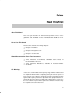
Related Documentation From Texas Instruments Preface Read This First About This Manual This users guide describes the characteristics, operation, and use of the UCC2977 CCFL backlight converter evaluation module (EVM). The users guide includes a schematic diagram, bill of materials and test results.
iv
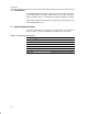
Contents Contents 1 Hardware . . . . . . . . . . . . . . . . . . . . . . . . . . . . . . . . . . . . . . . . . . . . . . . . . . . . . . . . . . . . . . . . . . . . . . . 1.1 Introduction . . . . . . . . . . . . . . . . . . . . . . . . . . . . . . . . . . . . . . . . . . . . . . . . . . . . . . . . . . . . . . . . 1.2 Operating Specifications . . . . . . . . . . . . . . . . . . . . . . . . . . . . . . . . . . . . . . . . . . . . . . . . . . . . . 1.3 Schematic . . . . . . . . . . . . . . . . . . . . . . .
Contents Figures 1–1 1–2 1–3 1–4 3–1 3–2 3–3 3–4 3–5 3–6 3–7 3–8 3–9 3–10 UCC2977EVM Schematic . . . . . . . . . . . . . . . . . . . . . . . . . . . . . . . . . . . . . . . . . . . . . . . . . . . . . . Top Silk Screen With Top Copper Layer . . . . . . . . . . . . . . . . . . . . . . . . . . . . . . . . . . . . . . . . . . Top Layer Copper . . . . . . . . . . . . . . . . . . . . . . . . . . . . . . . . . . . . . . . . . . . . . . . . . . . . . . . . . . . . . Bottom Layer Copper . . . . . . . . . . . . .
Chapter 1 Hardware The UCC2977 evaluation module (SLUP178) provides a reference design for evaluating the performance of a high efficiency CCFL backlight converter using the UCC2977 (push-pull backlight controller). The device contains all of the circuitry necessary to control a backlight converter. This chapter contains the schematic, board layout, and the bill of materials. The evaluation module (EVM) performance specifications are also given. Topic Page 1.1 Introduction . . . . . . . . . . . . . . .
Introduction 1.1 Introduction The UCC2977 EVM (SLUP178) is a 1.8-W dc/ac inverter module used to drive a cold cathode fluorescent lamp (CCFL) with a piezoelectric transformer (PZT). This EVM consists of a push-pull circuit using the UCC2977 controller. The principle of operation for the inverter is explained in the application section of the UCC2977 data sheet. 1.2 Operating Specifications This section summarizes the performance specifications of the SLUP178 converter.
Schematic 1.3 Schematic Figure 1–1.
Bill of Materials 1.4 Bill of Materials Table 1–2. Bill of Materials Required for the UCC2977 (SLUP178) Count 1-4 Ref Des Description Size MFR Part Number 1 C1 Capacitor, ceramic, 2200 pF, 50 V, X7R, 20% 603 Murata GRM188R71H222KA01 1 C2 Capacitor, ceramic, 220 pF, 50 V, X7R, 20% 603 Murata GRM188R7H221KD01 2 C3, C7 Capacitor, ceramic, 0.1 µF, 25 V, X7R, 20% 805 Murata GRM21BR71E104KA01 1 C4 Capacitor, ceramic, 0.
Board Layout 1.5 Board Layout Figure 1–2. Top Silk Screen With Top Copper Layer Figure 1–3. Top Layer Copper Figure 1–4.
1-6
Chapter 2 Design Procedure This chapter describes how to design the UCC2977EVM. Topic Page 2.1 Push-Pull Inductor Selection . . . . . . . . . . . . . . . . . . . . . . . . . . . . . . . . . . . 2-2 2.2 Frequency Range Setting . . . . . . . . . . . . . . . . . . . . . . . . . . . . . . . . . . . . . . 2-2 2.3 Analog Dimming of the Lamp . . . . . . . . . . . . . . . . . . . . . . . . . . . . . . . . . . 2-2 2.4 Open-Lamp Voltage Programming . . . . . . . . . . . . . . . . . . . . . . . . . . . . .
Push-Pull Inductor Selection 2.1 Push-Pull Inductor Selection The push-pull topology requires a different approach for calculating the external inductor values. Referring to Figure 1–1, Q2A and Q2B are driven out of phase at 50% duty cycle. When Q2A is on, current is ramped up in L1. During the next switch cycle Q2B is turned on, Q2A is turned off, and the energy stored in L1 is transferred through the piezoelectric transformer.
Open-Lamp Voltage Programming Zero volts on VAD commands full current while 3 V commands minimum current. For the initially configured EVM, maximum current is 4.8 mA. R15 is selected to be 909 Ω setting VAD to 0 V and lamp current to 4.8 mA. With R2 set to 150 K, R10 is calculated to be 50 K. The control-voltage to lamp-current equation for the EVM is: I LAMP(mA) + 4.89 * 1.22 (4) V AD 2.
Burst Dimming 2.7 Burst Dimming Burst dimming can be implemented at the OPEN/SD pin at the cost of open-lamp detection. Connect pin 2 to pin 3 of JP1 to disable the open-lamp detection circuit during burst dimming mode. Since the feedback loop does not need to operate with minimum lamp current (as with analog dimming), the feedback capacitor, C4, can be reduced to 22 nF to improve the response time when the lamp restrikes.
Chapter 3 Test Results This chapter describes how to properly connect and setup the UCC2977EVM. It also presents the test results, which cover efficiency, burst dimming, and open-lamp protection. Topic Page 3.1 Test Setup . . . . . . . . . . . . . . . . . . . . . . . . . . . . . . . . . . . . . . . . . . . . . . . . . . . . 3-2 3.2 Test Results . . . . . . . . . . . . . . . . . . . . . . . . . . . . . . . . . . . . . . . . . . . . . . . . . .
Test Setup 3.1 Test Setup 3.1.1 Lighting CCFL A power supply with a power capability of 6 V/0.5 A is required for this test. Figure 3–1 shows the input/output connections to the SLUP178. Connect a 270-V lamp (BF3100–20B). Connect pin 1 to pin 2 of jumper JP1. Figure 3–1.
Test Setup 3.1.2 Analog Dimming Test For analog dimming, enable the open-lamp detection by connecting pin 1 to pin 2 of jumper JP1. A power supply that has a power capability of 6 V/0.5 A is required for this test. Figure 3–2 shows the input/output connections to the SLUP178. The lamp intensity is controlled by VAD (0~3 Vdc). Make sure the wire of the lamp is as short as possible and the lamp reflector (if there is one) is grounded to board ground.
Test Setup 3.1.3 Burst Dimming Test Connect pin 2 to pin 3 of JP1 to disable the open-lamp detection circuit during burst dimming. A low frequency ( >100 Hz) 0~4 V square wave applied to BD modulates the lamp current. Figure 3–3.
Test Results 3.2 Test Results The test results for the SLUP178 are shown in this section. Figure 3–4. Efficiency With a Low Profile Sumida Inductor (CDRH6D28; 22 µH, 128 mΩ, 6.7 × 6.7 × 3 mm) EFFICIENCY vs INPUT VOLTAGE 90 85 4.7 mA 80 Efficiency – % 4 mA 75 3 mA 70 65 60 2 mA 55 50 3 4 5 VI – Input Voltage – V 6 Figure 3–5. Efficiency With a High Profile Toko Inductor (646CY–220M; 22 µH, 115 mΩ, 7.6 × 7.6 × 5.1 mm) EFFICIENCY vs INPUT VOLTAGE 90 4.
Test Results Figure 3–6. Transformer Input/Output Voltages at VI = 3 V (CH1=Primary 1, CH4=Primary 2, M1=Transformer Primary Voltage, CH3=Lamp Voltage) Figure 3–7. Transformer Input/Output Voltages at VI = 6 V (CH1=Primary 1, CH4=Primary 2, M1=Transformer Primary Voltage, CH3=Lamp Voltage) Figure 3–8.
Test Results Figure 3–9. Burst Dimming With 80% Duty Cycle (CH1=Burst Dimming Control Signal, CH3=Lamp Voltage) Figure 3–10.
3-8