
Datasheet

Isolation
Amplifier
COMMUNICATION
(Programming & Status Reporting)
141
12
8
VDD
PVDD
CS
10OUT2
3
4
2
5
6
IN1
AGND
3V3
IN2
CLF
7
UCD7201PWP
11OUT1
9PGND
13
NC
ILIM
NC
Bias Supply
Bias Winding
VIN
VOUT
DIGITAL
CONTROLLER
GND
PWMA
ADC4
INTERRUPT or CCR
PWMB
ADC3
VCC
PWM or GPIO
ADC1
ADC2
UCD7201
www.ti.com
SLUS645E –FEBRUARY 2005–REVISED NOVEMBER 2009
Digital Control Compatible Dual Low-Side ±4 Amp MOSFET Drivers with Programmable
Common Current Sense
Check for Samples: UCD7201
1
FEATURES
DESCRIPTION
2
• Adjustable Current Limit Protection
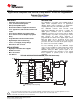
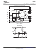
The UCD7201 is a member of the UCD7K family of
digital control compatible drivers for applications
• 3.3-V, 10-mA Internal Regulator
utilizing digital control techniques or applications
• DSP/μC Compatible Inputs
requiring fast local peak current limit protection.
• Dual ±4-A TrueDrive™ High Current Drivers
The UCD7201 includes dual low-side ±4-A
• 10-ns Typical Rise and Fall Times with 2.2-nF
high-current MOSFET gate drivers. It allows the
Loads
digital power controllers such as UCD9110 or
• 20-ns Input-to-Output Propagation Delay
UCD9501 to interface to the power stage in double
ended topologies. It provides a cycle-by-cycle current
• 25-ns Current Sense-to-Output Propagation
limit function for both driver channels, a
Delay
programmable threshold and a digital output current
• Programmable Current Limit Threshold
limit flag which can be monitored by the host
• Digital Output Current Limit Flag
controller. With a fast cycle-by-cycle current limit
protection, the driver can turn off the power stage in
• 4.5-V to 15-V Supply Voltage Range
the event of an overcurrent condition.
• Rated from -40°C to 105°C
For fast switching speeds, the UCD7201 output
stages use the TrueDrive™ output architecture, which
APPLICATIONS
delivers rated current of ±4 A into the gate of a
• Digitally Controlled Power Supplies
MOSFET during the Miller plateau region of the
• DC/DC Converters
switching transition. It also includes a 3.3-V, 10-mA
• Motor Controllers
linear regulator to provide power to the digital
• Line Drivers controller.
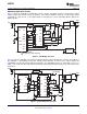
TYPICAL APPLICATION DIAGRAM (Push-Pull Converter)
1
Please be aware that an important notice concerning availability, standard warranty, and use in critical applications of Texas
Instruments semiconductor products and disclaimers thereto appears at the end of this data sheet.
2TrueDrive, PowerPAD are trademarks of Texas Instruments.
PRODUCTION DATA information is current as of publication date.
Copyright © 2005–2009, Texas Instruments Incorporated
Products conform to specifications per the terms of the Texas
Instruments standard warranty. Production processing does not
necessarily include testing of all parameters.