Using the UCD9224EVM-464 User's Guide Literature Number: SLUU443 March 2011
User's Guide SLUU443 – March 2011 UCD9224EVM-464 Digitally Controlled Dual-Rail POL 1 This user guide describes the evaluation module (EVM) for the UCD9224 Digital PWM System Controller and the UCD7242 Digital Dual Synchronous Buck Power Driver. The UCD9224 is a multi-rail, multi-phase synchronous buck digital PWM controller designed for non-isolated DC/DC power applications.
Description www.ti.com 2.
Description www.ti.com PTD08D210W Module • Dual 10-A Outputs • Programmable Wide-Output Voltage – 0.7 V to 3.6 V • 4.75-V to 14-V Input Voltage • Efficiencies up to 96% • Digital I/O – PWM input – Fault Flag (FF) output – Synchronous Rectifier Enable (SRE) input • Analog I/O – Temperature Output – Output Current reporting • Operating Temperature: -40°C to 85°C UCD7242 Driver • Fully Integrated Power Switches and Drivers for Dual Synchronous Buck Converters • Wide Input Voltage Range of 4.
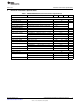
Electrical Performance Specifications www.ti.com 3 Electrical Performance Specifications Table 1. UCD9224EVM-464 Electrical Performance Specifications PARAMETER TEST CONDITIONS MIN TYP MAX UNITS Input Characteristics Voltage range As configured, EVM input capable of 4.75 V to 14.0 V 10.8 No load input current 12 13.
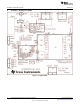
Assembly / Schematic Layouts 4 www.ti.com Assembly / Schematic Layouts Figure 1.
Assembly / Schematic Layouts www.ti.com Figure 2.
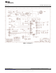
Assembly / Schematic Layouts www.ti.com Figure 3.
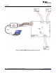
Test Setup www.ti.com 5 Test Setup 5.1 Test Equipment Input Voltage Source: 12-V power supply with at least a 5-A sourcing capability. Multimeters: Two 5 ½ digit digital multimeters. Output Load: Two electronic loads capable of sinking 10 A from low voltage (<1 V) sources. Oscilloscope: Minimum 4-channel, 100-MHz bandwidth with storage capability. Fan: Not required but may be desirable if testing at full output power. Recommended Wire Gauge: Input Voltage: 20 AWG min. Output Load: 16 AWG min. 5.1.
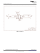
Test Setup 5.2 www.ti.com Recommended Test Setup Figure 4.
Test Setup www.ti.com 5.3 List of Connectors Table 2. Connector definition CONNECTORS PINS NAME J1 1 VIN Input voltage 2 GND Input voltage return J2 1 thru 4 GND USB interface adapter - unconnected 5 USB interface adapter – 3.
Test Setup 5.4 www.ti.com List of Test Points Table 3.
Software Setup www.ti.com 6 Software Setup Accessing the UCD9224EVM-464’s configuration, control and monitoring capabilities with the Fusion Digital Power Designer software tool requires a one-time software setup per host system. 6.1 Fusion Digital Power Designer Software (Fusion GUI) Installation Place the Fusion Digital Power Designer Software (Fusion GUI) Installer zip file (UCD9224EVM-464 Software Files) in a known location on the host computer to be used for EVM configuration/test.
Test Procedure 7.2 www.ti.com Output Voltage 1. Attach the DMMs to both output voltage test points, +VOUT1 to PGND and +VOUT2 to PGND. 2. Enable the external input voltage supply. 3. Measure VOUT1 and VOUT2 Output Voltages. 7.3 VIN UVLO Settings and OVP Setpoint 1. 2. 3. 4. 5. 6. 7.4 Remove the DMM from VOUT2 and connect to the input voltage test points, VIN and PGND. Slowly reduce the external input voltage supply until VOUT1 is disabled then confirm VIN voltage level.
Test Procedure www.ti.com 7.5 Fusion GUI Monitoring and Control Example 1. Attach the USB Interface Adapter to the computer hosting the Fusion GUI software with the supplied USB A-to-MiniB cable then to the UCD9224 with the supplied 10-pin ribbon cable. The USB Interface Adapter will be recognized as an HID device by the host system with no additional drivers needed. The green LED will illuminate when the adapter has been connected with the system. 2.
Test Procedure www.ti.com 4. Select the Monitor Page and the window in Figure 7 will be displayed. The operating status of the output voltage and other parameters for Rail #1 can be reviewed from this window, by default Rail #1 is always presented at the Fusion GUI startup. Rail #2 can be monitored by using the dropdown selection in the upper right corner of the monitoring window and selecting UCD9224 @ Address xxx Rail #2.
Test Procedure www.ti.com 5. There are configuration value boxes in many of the plot windows, ex. OT Fault and OT Warn boxes exist within the Temp Rail #1 plot. These are the numerical values for the fault and warning limits and reflect the same values found on the Configuration page of the GUI.
Test Procedure 7.6 www.ti.com Restoring the UCD9224 EVM’s Original Configuration The file HPA464_EVM_Default_Configuration.XML can be found on the TI website and is provided to allow the user to return the EVM to its originally configured state. Simply open the Fusion GUI while the powered EVM is connected to the computer with the USB Interface Adapter.
Performance Data and Typical Characteristic Curves www.ti.com 8 Performance Data and Typical Characteristic Curves Figure 9 through Figure 12 present typical performance curves for UCD9224EVM-464. 8.1 Efficiency EFFICIENCY vs LOAD CURRENT 100 90 80 – Efficiency - % 70 60 50 40 30 20 10 10.0 V 12.0 V 13.2 V 0 0 2 4 6 8 10 12 ILOAD – Load Current - A Figure 9. 2.5-V Efficiency (1.2-V no load) 8.
Performance Data and Typical Characteristic Curves www.ti.com Figure 11. 2.5-V Output Ripple Figure 12. 1.
EVM Assembly Drawing and PCB layout www.ti.com 9 EVM Assembly Drawing and PCB layout The following figures (Figure 13 through Figure 17) show the design of the UCD9224EVM-464 printed circuit board. Figure 13.
EVM Assembly Drawing and PCB layout www.ti.com Figure 14.
EVM Assembly Drawing and PCB layout www.ti.com Figure 15.
EVM Assembly Drawing and PCB layout www.ti.com Figure 16.
EVM Assembly Drawing and PCB layout www.ti.com Figure 17.
List of Materials 10 www.ti.com List of Materials The EVM components list according to the schematic shown in Figure 2 and Figure 3. Table 4. UCD9224EVM-464 List of Materials QTY 26 REFERE NCE 3 C1, C2, C3 4 DESCRIPTION Capacitor, ceramic, 4.
Evaluation Board/Kit Important Notice Texas Instruments (TI) provides the enclosed product(s) under the following conditions: This evaluation board/kit is intended for use for ENGINEERING DEVELOPMENT, DEMONSTRATION, OR EVALUATION PURPOSES ONLY and is not considered by TI to be a finished end-product fit for general consumer use. Persons handling the product(s) must have electronics training and observe good engineering practice standards.
IMPORTANT NOTICE Texas Instruments Incorporated and its subsidiaries (TI) reserve the right to make corrections, modifications, enhancements, improvements, and other changes to its products and services at any time and to discontinue any product or service without notice. Customers should obtain the latest relevant information before placing orders and should verify that such information is current and complete.