
Datasheet


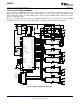
Table Of Contents
- FEATURES
- APPLICATIONS
- DESCRIPTION
- ELECTRICAL SPECIFICATIONS
- ABSOLUTE MAXIMUM RATINGS
- RECOMMENDED OPERATING CONDITIONS
- ELECTRICAL CHARACTERISTICS
- ADC MONITORING INTERVALS AND RESPONSE TIMES
- HARDWARE FAULT DETECTION LATENCY
- PMBus/SMBus/I2C
- I2C/SMBus/PMBus Timing Characteristics
- FUNCTIONAL OVERVIEW
- PMBus Interface
- Resistor Programmed PMBus Address Decode
- JTAG Interface
- Bias Supply Generator (Series Regulator Controller)
- Power On Reset
- External Reset
- Output Voltage Adjustment
- Analog Front End (AFE)
- Digital Compensator
- DPWM Engine
- Flexible Rail/Power Stage Configuration
- DPWM Phase Distribution
- DPWM Synchronization
- Phase Shedding at Light Current Load
- Phase Adding at Normal Current Load
- Output Current Measurment
- Output Current Balancing
- Overcurrent Detection
- Current Foldback Mode
- Input Voltage and Current Monitoring
- Temperature Monitoring
- Temperature Balancing
- Soft Start, Soft Stop Ramp Sequence
- Input UV Lockout
- Voltage Tracking
- Sequencing
- Fan Control
- Non-volatile Memory Error Correction Coding
- APPLICATION INFORMATION

1
FEATURES
APPLICATIONS
DESCRIPTION
UCD9240
www.ti.com
................................................................................................................................................... SLUS766C – JULY 2008 – REVISED NOVEMBER 2008
Digital PWM System Controller
• Supported by Fusion Digital Power™
Designer, a Full Featured PC Based Design
2
• Fully Configurable Multi-Output and
Tool to Simulate, Configure, and Monitor
Multi-Phase Non-Isolated DC/DC PWM
Power Supply Performance.
Controller
• Controls Up To Four Voltage Rails and Up To
Eight Phases
• Industrial/ATE
• Supports Switching Frequencies Up to 2MHz
• Networking Equipment
With 250 ps Duty-Cycle Resolution
• Telecommunications Equipment
• Up To 1mV Closed Loop Resolution
• Servers
• Hardware-Accelerated, 3-Pole/3-Zero
• Storage Systems
Compensator With Non-Linear Gain for
• FPGA, DSP and Memory Power
Improved Transient Performance
• Supports Multiple Soft-Start and Soft-Stop
Configurations Including Prebias Start-up
The UCD9240 is a multi-rail, multi-phase
• Supports Voltage Tracking, Margining and
synchronous buck digital PWM controller designed for
Sequencing
non-isolated DC/DC power applications. This device
• Supports Current and Temperature Balancing
integrates dedicated circuitry for DC/DC loop
for Multi-Phase Power Stages
management with flash memory and a serial interface
to support configurability, monitoring and
• Supports Phase Adding/Shedding for
management.
Multi-Phase Power Stages
• Sync In /Out Pins Align DPWM Clocks
The UCD9240 was designed to provide a wide
variety of desirable features for non-isolated DC/DC
Between Multiple UCD9240 Devices
converter applications while minimizing the total
• Fan Monitoring and Control
system component count by reducing external
• 12-Bit Digital Monitoring of Power Supply
circuits. The solution integrates multi-loop
Parameters Including:
management with sequencing, margining, tracking
and intelligent phase management to optimize for
– Input Current and Voltage
total system efficiency. Additionally, loop
– Output Current and Voltage
compensation and calibration are supported without
– Temperature at Each Power Stage
the need to add external components.
• Multiple Levels of Overcurrent Fault
To facilitate configuring the device, the Texas
Protection:
Instruments Fusion Digital Power™ Designer is
– External Current Fault Inputs
provided. This PC based Graphical User Interface
offers an intuitive interface to the device. This tool
– Analog Comparators Monitor Current
allows the design engineer to configure the system
Sense Voltage
operating parameters for the application, store the
– Current Continually Digitally Monitored
configuration to on-chip non-volatile memory and
• Over and Undervoltage Fault Protection
observe both frequency domain and time domain
simulations for each of the power stage outputs.
• Overtemperature Fault Protection
• Enhanced Nonvolatile Memory With Error
TI has also developed multiple complementary power
stage solutions – from discrete drives in the UCD7k
Correction Code (ECC)
family to fully tested power train modules in the PTD
• Device Operates From a Single Supply With an
family. These solutions have been developed to
Internal Regulator Controller That Allows
complement the UCD9k family of system power
Operation Over a Wide Supply Voltage Range
controllers.
1
Please be aware that an important notice concerning availability, standard warranty, and use in critical applications of Texas
Instruments semiconductor products and disclaimers thereto appears at the end of this data sheet.
2 Fusion Digital Power, Auto-ID are trademarks of Texas Instruments.
PRODUCTION DATA information is current as of publication date.
Copyright © 2008, Texas Instruments Incorporated
Products conform to specifications per the terms of the Texas
Instruments standard warranty. Production processing does not
necessarily include testing of all parameters.