TEXAS MEMORY SYSTEMS, INC. RamSan-500 User’s Manual RamSan-500 Version 1.
Revision History The following table describes revisions to this document: Version 1.0 Comments Initial release Date 9/14/2007 Any trademarks or registered trademarks used in this document belong to the companies that own them. RamSan-500 User’s Manual 2 of 48 Copyright © 2007, Texas Memory Systems, Inc. All rights are reserved.
Table of Contents Chapter 1 – Introduction .................................................................................. 4 1.1 Overview ............................................................................................... 4 1.2 System Components ............................................................................... 4 1.3 Power ................................................................................................... 4 1.4 Reliability .........................................
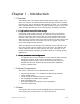
Chapter 1 – Introduction 1.1 Overview The RamSan-500 is the World’s Fastest Flash-based storage system. The basic unit contains nine RAID-protected Flash storage modules accessible from the front, with a combined usable capacity of either 1 or 2-Terabytes and a data bandwidth of 2 GB/sec. A single RamSan-500 fits in 4U of rack space. Multiple RamSan-500 units scale capacity, bandwidth, and IOPS. 1.1.
1.4 Reliability The RamSan-500 is designed to offer superior reliability to other solidstate disks and RAID devices. Its standard features include Chipkill™protected RAM, hot-swap modular Flash memory, hot-swap power supplies, failover ports, and SNMP compatibility. The nine-unit RAID design ensures data integrity even in the event of the complete failure of a single Flash module. In order to reduce the probability of a Flash module failure, the unit incorporates multiple error-correcting methods. 1.
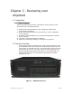
Chapter 2 – Reviewing your shipment 2.1 Unpacking 2.1.1 System Inspection TMS ships the RamSan-500 with a packing list. Ensure that you have received all of the components listed. 1) Examine the external chassis for any damage that might have occurred during shipping. 2) Examine the Flash modules to ensure that they were not damaged during shipping. 3) Inspect the interface plate for any screws that might have loosened during shipping. 4) Inspect the front panel display for damage.
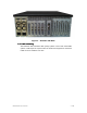
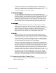
Figure 2 – RamSan-500 Back 2.2.1 Rack mounting The RamSan-500 solid-state disk (SSD) system is a 4U rack-mountable system. TMS ships the system with the slides and equipment needed to install it into a standard 19” rack.
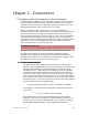
Chapter 3 – Connections 3.1 Installing a Host Bus Adaptor in the Host System Host Bus Adapters (HBAs) provide an interface from the server’s PCI bus to Fibre Channel attached devices. HBAs are available from a variety of vendors. Before purchasing an HBA, ensure that it provides a driver for the Operating System (OS) version that you are using. Before installing the HBA, consult your server’s documentation to determine which one of its PCI slots is on the fastest and least congested PCI bus (see Section 3.
connections requires one of the following solutions: multi-pathing software to a single LUN, using software to stripe across multiple LUNs, accessing multiple LUNs on the RamSan-500 concurrently, or connecting multiple servers to the system. 3.1.2 Host Bus Adapter You can modify some HBA settings to increase performance. For information specific to your HBA, consult the HBA documentation.
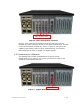
Fibre Channel Ports Figure 3– Fibre Channel Port Locations Figure 3– Fibre Channel Port Locations shows the port layout for the RamSan-500. Each controller has two or four Fibre Channel ports: A and B, on the top and bottom respectively. The FC-77 ports on the system are capable of connecting to point-to-point, arbitrated loop, and switched fabric topologies at either 4-Gigabit or 2-Gigabit speeds. 3.
3.4 Connecting Power to the System A fully loaded RamSan-500 requires approximately 250 watts of power. It contains redundant power supplies that are hot-swappable. Using the AC power cords provided, connect each power module to a power source. Install the socket outlet in an easily accessible location near the equipment. Power Supplies Figure 5 – RamSan-500 Power Supply The power supply includes the following button and indicators: 3.4.
Chapter 4 – Getting Started This chapter will guide you through setting up your RamSan-500. It is important to accomplish the following tasks to make your system usable: Use the front panel display to set up the network (Section 4.5) Get the Web monitor operational (Section 4.7) Use the Web monitor to set the date and time (Section 4.8) Use the Web monitor to configure advanced network settings (Section 4.9) Use the Web monitor to configure security (Section 4.
4.3 Front Panel Display Basics The front panel display provides a quick and easy way to view the RamSan-500’s status. It displays the current progress of Flash module synchronization and shows system warnings and failures. The RamSan-500’s front panel allows you to: Inspect the state of the system Select a Flash module to power off Change the method of IP address assignment Reboot/Shutdown the system.
Selecting “Flash Module” allows you to select a module to identify mode or for power off. Main Menu Flash Module Selecting “Active Monitor Mode” changes the default front panel display to show port activity across both display lines. This makes it easier to view from a distance. This option becomes “Remove Monitor Mode” once it has been set.
To shut down the system using the front panel, use the arrow buttons to cycle through the top-level menu to select “Manual Shutdown”. Use the Select button to select this menu item. The display prompts you to confirm that you wish to “Power Off System”. To cancel the shutdown, use the ↑ button to return to the main menu. To proceed with the shutdown, use the ↓ button to confirm the system power off. Now, the front panel display indicates that the system is powering off.
menu and choose the “Identify Module” option. Next, scroll down the Identify Module sub-menu to choose the module that you wish to Identify. After a Module is selected it Status Indicator LED will slowly blink Orange for four second and then return to its previous state. Identify Module Module 1 Once the appropriate module has been identified it may be powered off from the front panel.
4.4.3 Manual Restart The administrator can reboot the RamSan manually from the front panel display. This procedure safely synchronizes all data in RAM to the internal Flash module storage, powers off for around 5 seconds, and then powers back on. To shut down the system using the front panel, use the arrow buttons to cycle through the top-level menu to select “Manual Restart”. Use the Select button to select this menu item. The display prompts you to confirm that you wish to “Restart System”.
To set up the network via the front panel, use the arrow buttons to cycle through the top-level menu options until the display shows “Network Config”. Use the Select button to choose this option and continue with the configuration. You may now use the arrow buttons to scroll through the following menu options: Displays a list of the current IP configuration, hostname, IP address, subnet mask, gateway address (if applicable), and hardware Ethernet address.
After you have chosen “Static IP”, the display prompts you to enter an address. Use the ↑ and ↓ buttons to move the cursor. Hit Select to pick a number. And then use the ↑ and ↓ buttons to cycle through the numbers 0 through 9. To save the changed value, press the Select button. To revert to the previous value, press the Menu button. Ethernet IP address: 192.000.000.000 After you have finished entering the IP address, scroll the cursor off the end – this brings up the “Network Subnet Mask” screen.
MAC address. Use this value to configure your DHCP server. Re-enter the “Network Config” menu, then “Set IP Config” menu and select “DHCP”. Set IP Config DHCP The next screen commits the changes and automatically restarts the network. Use DHCP for IP? ↓ Yes ↑ No You should witness the network restarting. Restarting Network... The final screen displays the IP address assigned by the DHCP server. New IP Address: 192.168.111.
4.6.2 Connecting using Telnet Once the administrator configures the Ethernet port on the RamSan-500 using either the front panel or the serial port, you may remotely monitor the system using a Telnet session. Set your terminal settings to VT100 mode. To learn more about managing the RamSan-500 using the serial port or Telnet connections, see the RamSan Command Line Interface Manual available from Texas Memory Systems. 4.6.
4.7.1 Acquiring the System IP Address To use the Web monitor, you must connect to it over your network. You will need to acquire the RamSan-500’s IP address – which can be accomplished from the front panel display. Press the Menu button to display the “Main Menu”. Use the ↓ and ↑ buttons to find the “System Info” option. Tap the Select key. Main Menu System Info Use the ↓ button to scroll until you see the “IP Address” line and the line below it. Take note of the IP address. ↑ IP Address: ↓ 192.168.
After you log in, the window shown in Figure 7 will appear. Figure 7 – Web Monitor Opening Screen From here select the RamSan icon. When selected it shows a variety of information about the system.
A great deal of information is available in this monitor: firmware versions, system event warnings, environmental information, and system statistics. 4.8 Date and time setup with the Web monitor When you acquire the system, it is important to verify that the date and time are correct. If they are incorrect, you can use the Web monitor to change them. From the Web monitor, expand the “Management” tab under the “System List”. This will expose three sub-options.
Figure 10 – Web Monitor Calendar By configuring the calendar, you will set the date and time of the RamSan-500. Additionally, the RamSan-500 supports NTP (Network Time Protocol). 4.9 Network Configuration with the Web Monitor You should have already set up the basic network options via the front panel if you followed the instructions in Section 4.5 – Network Configuration with the Front Panel Display. The Web monitor allows you to change those options as well.
To modify the network configuration, right-mouse click and select “Network config…” or left-mouse click the globe/wrench icon in the button bar. Both methods bring up the network configuration window. Figure 12 – Web Monitor Network Configuration You can manipulate the network settings and then select “OK”. The settings will be saved and the system’s network will be restarted. You should see several system messages displayed in the “Recent Event Log” panel of the Web monitor confirming your settings. 4.
Figure 13 – Web Monitor Management Options A user management table window pops up and displays all current users in the system. By default, there are only two users, please see Figure 14 for a screenshot. Figure 14 – Web Monitor User Management Please change the password to your high-privileged user account (named “admin”) by selecting the user and left-clicking the “Password…” button. This will pop up the “Change User” window shown in Figure 15.
Figure 15 – Web Monitor Change User Type in the new password and confirm it. Hit the “OK” button when finished. 4.10.3 Adding Users You can add new users by selecting the “Add…” button in the “User Management” window. Doing so will bring up the “Add User” window shown in Figure 16. Figure 16 – Web Monitor Add User You can add high-privileged users by assigning the new user to the “admins” group. You can give the new user low-privileges by assigning them to the “users” group. 4.
Figure 17 – Web monitor Logical Unit A wizard will open to guide you through the Logical Unit creation process. After reading the overview, click the “Next” button to set the Logical Unit Parameters. The parameters window is shown in Figure 18. Figure 18 - Web Monitor Logical Unit Parameters The parameters available for the Logical Unit are: • Name – This is a user defined name for the LUN to make it easily identifiable. • Number – This is the Logical Unit Number (LUN) that is presented to the host.
o Writethrough – Force all of the writes to be written to Flash before acknowledging the write as complete. • Device ID – This is an OpenVMS specific identifier. • Report corrected media errors to the SCSI host – This controls whether any internal corrected errors are reported over the SCSI layer to the host. By default it is enabled. For most environments this should be set.
Figure 20 - Web Monitor Access Policy Table To create and access policy, click the “Add” button. This opens a window that allows you to define the parameters of the access policy, shown in Figure 21. Figure 21 - Web Monitor Add Access Policy To create an access policy, present the Logical unit to a host, then select a “Controller Port” on the RamSan.
4.12 Configuring the RamSan-500 Cache The RamSan-500 contains a large RAM cache to buffer write operations and keep the back and Flash busy with parallel operation. The cache details and configuration can be viewed by selecting the “Cache” item from under the “Storage” node of the system tree. The cache “Detailed Information” is shown in Figure 22. Figure 22 - Web Monitor Cache Detailed Information The detailed information includes information about the cache and its current configuration.
There are four different configuration options, Tuning, Read Ahead, Sync Always, and Dirty Threshold Percent. There are several options for each of these parameters that affect the behavior of the Cache: • Tune Cache For – This parameter controls the cache line size and how the Cache works with the back end Flash Array. The two options are: o IOPS – Use a smaller cache line size and send smaller accesses to the RAID controller.
Figure 24 – Web Monitor Logs The log events displayed in Figure 24 – Web Monitor Logs are not indicative of a shipped system. Sometimes it is valuable to save the RamSan logs made available from the Web monitor. To save the system event log, right mouse click the “Logs” item in the “System List”, then select “Save Log…” Or you can just left-click on the Flash icon under the menu bar in the button bar while the “Logs” item is highlighted.
Figure 25 – Web Monitor Log Options Once you select the “System Report…” option, a new window will appear and download the support log from the RamSan. It will take 10 to 20 seconds to complete. You can then hit the “Save” button in the lower right to save the support log to a file.
4.14 Upgrading the System with the Web Monitor It is easy to upgrade your RamSan using the Web monitor if you have a patch file. Patch files should be formatted “rs500-.patch”. From the Web monitor, expand the “Management” tab under the “Systems List”. This will expose three sub-options. Highlight “Firmware” – it will display the current RamSan-500 firmware version.
Either type in the path and file name of the patch or use the “Select…” button to browse for the file. When the file is selected, left-click the “Start” button. The firmware upgrade may take up to five minutes to complete. While the system is patching, a variety of messages will display in the “Recent Event Log” panel in the Web monitor. When the patch has completed, select the “Done” button. You will need to reboot your RamSan-500 for the patch to take effect.
Follow the information in Section 4.8 to get to the “Logs” item in the Web monitor “System List”. To clear the system event log, rightmouse click the “Logs” item and select “Clear Logs” – alternatively, left-mouse click the eraser icon in the button bar. This will clear the system event log.
Chapter 5 – System Maintenance Texas Memory Systems designed the RamSan-500 to be easily maintainable. You can update firmware from the Java interface and easily maintain the system components. You can hot swap the power supplies and Flash modules, which means that you can remove and replace these components while the system is running. ELECTRO-STATIC DISCHARGE WARNING PLEASE TAKE FULL E.S.D. PRECAUTIONS IF IT IS NECESSARY AT ANY TIME TO COME INTO CONTACT WITH ANY CIRCUIT BOARDS, COMPONENTS, OR CONNECTORS.
Power Supplies Figure 29 - Back of RamSan-500, Power Supply Location If the RamSan power supplies fail, they can be replaced while the power remains on to the system. There are three ways to detect a bad power supply. The easiest way is to examine the AC voltage LED. (See Figure 5 – RamSan-500 Power Supply.) If it is illuminated the power supply is running.
5.3 Flash Modules The RamSan-500 comes with 9 Flash modules in a RAID 5 configuration. This section will go over various failure conditions and what must be done to correct them. The Flash modules in the RamSan-500 are designed and manufactured by Texas Memory Systems. They incorporate proprietary technology to interface with the RamSan backplane and cannot by used outside of the RamSan-500.
OFF No Power, zone not present Because each Flash zone is independent of the other, the status of each zone may differ. WARNING REMOVING A FLASH MODULE WHILE IT IS POWERED ON MAY CAUSE IRREVERSIBLE DAMAGE TO THE MODULE. ONLY REMOVE A FLASH MODULE IF BOTH STATUS INDICATOR LEDS ARE OFF. 5.3.1 Flash Module Failure In addition to the error correct features built into the Flash module, the Flash modules are protected from a complete Flash module failure by a RAID configuration.
Figure 31 – Web Monitor Flash Module Failure Detection Figure 31 shows the Web monitor detecting a single bad Flash module. In this case, the module has been physically removed from the system so the Web monitor is reporting it missing. The module icons in the “System List” show a warning icon on all suspect components. Both “raid2” and “Flash 2” have been noted with warning icons (yellow triangled explanation points). WARNING REPLACE FAILED FLASH MODULES AS SOON AS POSSIBLE.
Figure 32 – Web Monitor RAID Degraded Detection WARNING MAKE CERTAIN THAT FLASH MODULES ARE POWERED OFF BEFORE REMOVING. The Web monitor reports higher-level information about a RAID that has a missing or bad Flash module. Figure 32 above shows the RAID information generated by removing the same Flash drive as shown in Figure 31. In this case, the removed module causes the RAID to be degraded, meaning the RAID cannot tolerate another Flash module error without data loss – but the RAID is still usable.
Figure 33 – Web Monitor RAID Rebuild Status If a Flash module fails and it is replaced with a new module, the RAID must be rebuilt. The RAID is usable while rebuilding, but performance is limited. WARNING IT IS RECOMMENDED THAT THE RAMSAN REMAIN UNUSED WHILE ANY RAID IS BEING REBUILT IF HIGH PERFORMANCE IS CRITICAL. REBUILDING RAID ARRAYS GREATLY IMPACTS SYSTEM THROUGHPUT. You can use the Web monitor to examine the status of the rebuilding process.
Figure 34 – Web Monitor RAID Offline You can access the Web monitor for more specific information on which RAID is offline. An example screenshot is shown in Figure 34. If the RAID has multiple module failures, it will be taken offline. There will be a good chance your RAID will lose its data. Please contact Texas Memory Systems to diagnose and repair your system (see Section 4.15.1 – Contacting Texas Memory Systems).
If a fan degrades in performance, the front panel display will show the fan’s speed. In this situation, the fan is still working, but it is not efficient. The error line displayed to the right scrolls across the bottom display row. System Status: WARN Errors: cage 1 fan 1 speed is below normal levels (6122.82 RPM) If a fan completely stops working an error is reported on the front panel display. The error line displayed to the right scrolls across the bottom display row.
Fan Bank 2 Fan Bank 1 Figure 36 – Top of an Open RamSan-500, Locations of the Fan Cages Please consult Figure 36 above to determine where each fan cage is in the chassis. Fans 1 through 8 are in Fan Bank 1, and fans 9 through 12 are in Fan Bank 2. Once you have extracted the fan cage, find the failed fan. There is a good chance that hair or dust has collected on the fan and all it needs is to be cleaned. Blowing compressed air into the axle of the fan can clear obstruction or debris.