
User's Manual


6
®
DEM-PCM1717
DEM-PCM1717-1
This demo board kit consist of a DEM-PCM1717 hardware
board, together with an interface cable, for connecting the
DEM-PCM1717 to power and connecting the software con-
trol lines to an IBM-PC parallel port. DEM-PCM1717 also
includes evaluation software, described later under Software
Description. The interface cable connects to the connector
CN2, a source of +5V and ground, and the parallel port of
an IBM compatible PC. Figure 5 shows the block diagram
and connection for the DEM-PCM1717-1.
DEM-DAI1717
DEM-DAI1717 is a complete evaluation fixture, including
an SPDIF receiver, PCM1717 and an analog post low-pass
filter DEM-DAI1717 also includes evaluation software.
PCM1717 contains features which can be programmed ex-
ternally. These features include a 256-step digital attenuator,
data interface format, word length, output format, etc. Refer
to the PCM1717 data sheet for a complete description of
these special functions.
PCM1717’s special functions are programmed via a 3-wire
serial interface. This type of control is commonly referred to
as serial or software control. The penalty for using this mode
is that the DAC must be controlled via external microproces-
sor or logic. But since most digital audio systems usually
contain a microprocessor or micro controller, component
count is not always increased.
DEM-DAI1717 utilizes the parallel port of an IBM-compat-
ible PC to implement the 3-wire serial programming inter-
face. The evaluation software runs on Windows
©
Operating
System.
The DEM-DAI1717 evaluation board consists of three main
sections or functions. The audio interface section consists of
an electrical (RCA jack) or fiber optics connector to the
SPDIF input. The input signal is processed into a standard 3-
wire serial digital audio interface with the SPDIF receiver.
The DAC section consists of the PCM1717E audio DAC
and its associated circuitry. The active filter section uses an
OPA2604 op amp to implement a 2nd-order filter for reduc-
tion of out-of-band noise. Figure 6 shows the block diagram
of the DEM-DAI1717 system board.
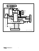
FIGURE 6. DEM-DAI1717 Block Diagram.
DAC
PCM1717
DAI-Receiver
CS8412
OPA2604
Low-Pass
FIlter
SPDIF Optical
TORX
174
Lch Filtered Out
Lch Direct Out
V out L
Mode Settings Centronics
S3
V out R
RCA: Connector
Rch Filtered Out
Rch Direct Out
RCA - 75Ω
+V
S
GND–V
S
+V
CC
GND
DAI-Settings
S0, S1, S2
JP
256fs
LRCK
BCK
DATA
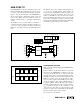
FIGURE 5. DEM-PCM1717-1 Interface Connection.
PC
Software
+5V, Ground
MC, MD, ML
Centronics
DEM-PCM1717
LRCK, BCK
DIN, SYSCLK
Left/Right Audio