
User's Manual


8
®
DEM-PCM1717
DEM-DAI1717 SYSTEM BOARD
INFORMATION
GENERAL SPECIFICATIONS
Table I lists the specifications for the DEM-DAI1717 sys-
tem board.
SPDIF Interface Optical via Toslink
RCA with 75Ω impedance.
System Clock Frequency 256 times sampling frequency, fs
Digital Audio Interface 16 bits, Normal Format, MSB last
18 bits, Normal Format, MSB last
I
2
S 16 or 18 bits
THD+N 0.004% typical, with internal 20kHz Low
Pass Filter.
0.08% typical, direct out, with external
30kHz Low Pass Filter.
Dynamic Range 94dB typical, (EIAJ method, A-weighted
filter)
SNR 100dB typical, (EIAJ method, A-weighted
filter)
Maximum Output 2Vrms (using internal low pass filter out)
+V
CC
range +4.5 to +5.5
+I
CC
+60mA (no external load) to +120mA
±V
S
±5V ~ ±15V
±I
S
±15mA (no external load)
TABLE I. DEM-DAI1717 General Specifications.
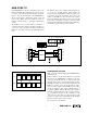
SPDIF INTERFACE OPTIONS
The DEM-DAI1717 employs a SPDIF receiver chip. This
receiver extracts 4 signals from a two wire signal that is
interfaced to the board. The receiver can supply these four
digital audio signals in up to eight different formats. Of these
formats only three are useful or valid for the PCM1717. The
output format is commanded by the setting switches S0, S1,
and S2. Figure 7 shows the switches and resulting output
configurations from the settings. Only the three configura-
tions shown will produce valid outputs from the PCM1717E.
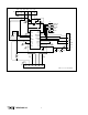
installed by default. An optional ground connection can be
made between the receiver chip and the PCM1717E. Refer
to Figure 8 for the orientation of these jumpers.
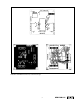
MODE CONTROL SWITCH SETTINGS
The DEM-DAI1717 system board uses 5 switches, labeled
as S3, to select between software and hardware control and
to provide settings for the hardware mode. When the DEM-
DAI1717 is to be used with the system software then it is
necessary for all of the mode switches to be in the high or
off position. Figure 9 shows the functions of all five of these
switches.
FIGURE 7. SPDIF Interface Options.
JUMPER SETTINGS
The DEM-DAI1717 system board has 5 jumpers blocks that
allow the digital outputs from the SPDIF receiver chip to be
connected to the PCM1717. The four jumpers that intercon-
nect the four digital audio signals from the receiver chip are
FIGURE 8. DEM-DAI1717 Jumper Configuration.
JP
CS8412 PCM1717E
256fs
LRCK
BCK
DATA
GND
FIGURE 9. DEM-DAI1717 Mode Control Switch Settings.
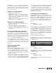
PARALLEL PORT CONNECTIONS
Figure 10 shows the connections made between the parallel
port connector and the pins on the PCM1717.
FIGURE 10. DEM-DAI1717 Parallel Port Connections.
1
2
3
4
5
19
18
36
PARALLEL PCM1717E
2
3
4
5
19 ~ 30
ML
MC
MD
RSTB
GND
L
S0
S0 S1
S2
SPDIF Output Format
H
L
L
L
H
H
H
H
L
16 bits Normal Format MSB First
18 bits Normal Format MSB First
I
2
S 16 or 18 bits
S1 S2
H
Mute
On
Mute
Off
Off
48kHz
44.1kHz
32kHz
Off
44.1kHz
DEM-DAI1717
48kHz
32kHz
Reset
Off
Reset
On
Hardware
Software
ML MC MD RSTB
Mode
On
Off
Low
High
De-Emphasis