TVP5158 Evaluation Module User's Guide Literature Number: SLEU108 November 2009
SLEU108 – November 2009 Submit Documentation Feedback Copyright © 2009, Texas Instruments Incorporated
1 2 3 4 5 6 7 8 9 10 ......................................................................................................................... 6 1.1 Functional Overview .................................................................................................... 6 1.2 Notational Conventions ................................................................................................. 6 Board Level Description ...................................................................................
www.ti.com List of Figures 1 TVP5158 EVM Block Diagram ............................................................................................ 7 2 TVP5158EVM System Level Block Diagram ............................................................................ 9 3 Location of TVP5158EVM Video/Audio Inputs ........................................................................ 11 4 TVP5158EVM Software Setup Wizard 5 Select Installation Folder .................................................
www.ti.com List of Tables 1 TVP5158EVM Jumper Descriptions ...................................................................................... 8 2 Jumper Settings for Stand-Alone Configuration ....................................................................... 11 3 Hardware Modifcation for I2S Audio to DM6467 ...................................................................... 12 4 Jumper Settings for DaVinci HD EVM as TVP5158 I2C Master ....................................................
User's Guide SLEU108 – November 2009 TVP5158 Evaluation Module 1 Description The TVP5158EVM evaluation module is a printed circuit board designed for evaluation of the TVP5158 Four-Channel PAL/NTSC Video Decoder. The TMS320DM6467 DVEVM (digital video evaluation module) can be used with the TVP5158EVM as a back-end video processor. This user guide outlines the necessary hardware and software setup required to provide full evaluation of the TVP5158. 1.
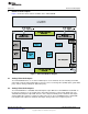
Board Level Description www.ti.com 2 Board Level Description Figure 1 shows the various features available on the TVP5158EVM. Figure 1. TVP5158 EVM Block Diagram 2.1 Analog Video/Audio Inputs The TVP5158EVM makes use of all the available inputs on the TVP5158 decoder, including four CVBS video inputs and four analog audio inputs. Connector J1 has four analog video (CVBS) inputs (yellow RCA jacks) and four analog audio inputs (white RCA jacks). 2.
Board Level Description 2.3 www.ti.com Digital Video/Audio Outputs to DaVinci HD EVM The TVP5158EVM has two dedicated connectors which match the digital video/audio input connectors on the DaVinci HD EVM. Connector J9 includes a 16-bit video data bus (buffered data from DVO_A and DVO_B of TVP5158), OCLK_P, OCLK_N, I2C and interrupts. The connector J10 includes BCLK, LRCLK and SD_R/SD_M outputs from TVP5158.
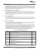
System Level Description www.ti.com Table 1.
Required Hardware and Equipment 4 www.ti.com Required Hardware and Equipment The required hardware and equipment are as follows: • Windows-based PC with Windows XP or later • Video sources (security camera, pattern generator, DVD player, etc.
Hardware Setup www.ti.com Video Inputs Audio Inputs CH2 CH4 CH2 CH4 CH1 CH3 CH1 CH3 Figure 3. Location of TVP5158EVM Video/Audio Inputs Table 2. Jumper Settings for Stand-Alone Configuration Jumper Designator W2, W1, W0 Setting TVP5158 I2C address selection 1-2, 1-2, 1-2 Comment Slave address 0xB0 (1011 LLL0) W3, W4 I2C master selection 1-2, 1-2 PC USB port controls TVP5158 I2C W7, W8 I2C connection to audio DAC ON, ON Connected W9 5.
Hardware Setup 5.2.1 www.ti.com Additional Setup when DSP Processes Video Only In this configuration, digital video goes to the DaVinci HD EVM. Digital I2S audio goes to the TLV320DAC32 Audio DAC on the TVP5158EVM. Stereo audio output can then be taken from the TVP5158EVM headphone jack. Make the following additional connections: 1. Samtec HQCD ribbon cable from TVP5158EVM DaVinci Video connector to the DaVinci HD EVM DC_P2 Video Expansion connector. 2.
Hardware Setup www.ti.com 5.2.3.1 DaVinci HD EVM as TVP5158 I2C Master Table 4 describes the jumper settings to set the DaVinci HD EVM as I2C master for the TVP5158. In this case, the Linux application and driver software control the entire system. Audio can be output from the TVP5158EVM or from the DaVinci HD EVM. See Section 5.2.1 and Section 5.2.2 for audio configurations. Table 4.
Software Installation www.ti.com Table 6.
Software Installation www.ti.com Figure 5. Select Installation Folder Figure 6.
Software Installation www.ti.com Figure 7.
TVP5158EVM Evaluation Procedures www.ti.com 7 TVP5158EVM Evaluation Procedures 7.1 Stand-Alone Operation - Non-Interleaved Digital Video Output Modes The following is the procedure for evaluation of TVP5158 for non-interleaved modes. The digital video output from TVP5158 is converted to analog component YPbPr video using a THS8200 Video/PC Graphics Triple DAC: 1. Double-click the TVP5158EVM Software icon on the Windows desktop to start the VCC application. 2.
TVP5158EVM Evaluation Procedures www.ti.com Figure 9. Specifying Cascaded Devices Figure 10. USB Device Not Found Error Message Figure 11.
TVP5158EVM Evaluation Procedures www.ti.com Figure 12. VCC Main Window - Set for Communication to All Decoders Figure 13. System Initialization for Analog Component YPbPr Video Output 7.2 7.2.1 Evaluation Using the DaVinci HD EVM Setting DM6467 ARM and DDR2 Memory Clock Rates For maximum performance, in a system using DM6467 and TVP5158(s) in the line-interleaved video modes, the DM6467 clock frequencies should be set as specified in Table 7. Table 7.
TVP5158EVM Evaluation Procedures www.ti.com Since the DaVinci HD EVM is not packaged with the TVP5158, it is usually necessary to program its NAND flash memory to the recommended clock frequencies, as described by the following procedure: 1. Unzip the UBL_DM646x_NAND_675_324.zip archive file onto the PC’s local hard drive. Suggested location is C:\UBL 2. Connect a null MODEM 9-pin serial cable from the DaVinci HD EVM UART connector to the PC COM1 serial port. 3.
TVP5158EVM Evaluation Procedures www.ti.com 7.2.2.2 Setup DaVinci HD Video / Audio Drivers Once the DaVinci HD EVM boot has completed, the login: prompt appears at the terminal. Copy and paste the Linux commands below to set up the video capture and and audio driver software. In place of , insert the directory path where the driver files are stored. root cd insmod cmemk.ko phys_start=0x87800000 phys_end=0x8ba00000 pools=1x1000 ./mapdmaq-hd insmod drv.
TVP5158EVM Evaluation Procedures www.ti.com Figure 15.
TVP5158EVM Evaluation Procedures www.ti.com 7.2.2.4 mcvip_test Demo Application The syntax and main menu of the mcvip_test (multi-channel video interface port) demo application is shown in Figure 16. Figure 16. mcvip_test Demo Application Menu 7.2.2.5 Procedure for Initializing Individual Video Formats The procedure for initializing the system for each individual video output format is as follows: 1. Start the mcvip_test application (do not enter the menu option yet). Example: ./mcvip_test.
TVP5158EVM Evaluation Procedures 7.3 www.ti.com Evaluation of Pixel-Interleaved Digital Video Output Modes The TVP5158EVM can be programmed for pixel-interleaved modes as described below. The DM6467 DaVinci HD EVM does not support pixel interleave modes, so a different back-end processor is required for this evaluation. 1. In the VCC System Initialization dialog box, click the Browse button. The Open dialog box shown in Figure 14 appears.
VCC Software in Depth www.ti.com 8 VCC Software in Depth 8.1 VCC Main Window The VCC main window contains the menu bar whose contents are summarized in Table 8. Table 8. VCC Main Menu Summary Menu Contents File Exit Edit Register Map – Edit I2C registers directly TVP5158 THS8200 Generic I2C – Edit I2C registers for any slave address Property Sheets – GUI controls for the I2C register map TVP5158 THS8200 Tools System Initialization – Initializes system using .
VCC Software in Depth www.ti.com Table 9. VCC Register Map Editor Controls Control Register Window Definition Scrolling text box that displays the address and data for the I2C registers that are defined for the device. This contains the I2C subaddress that will be accessed using the Write and Read buttons. Clicking on a row selects an address, which then appears in the address edit box. Address Edit Box NOTE: After clicking on a row, the Data Edit box contains the data that was in the register window.
VCC Software in Depth www.ti.com Table 11. Property Sheet Button Controls Button 8.3.1 Definition OK Writes to all writeable registers whose data has changed. A register is flagged as changed if the value to be written is different from the value last read from that address. Closes the dialog. Cancel Causes all changes made to the property page since the last Apply to be discarded.
VCC Software in Depth 8.4.4 www.ti.com Editing Tools vs Video Decoder Write Enables The behavior of the System Initialization, Edit Register Map and Property Sheets tools regarding the decoder write enables is described in Table 12. Figure 19. VCC Main Window – Configured for Broadcast Write Access (default) Figure 20. VCC Main Window – Configured for Single Video Decoder Write Access Table 12. Editing Tools vs Video Decoder Write Enables 8.
VCC Software in Depth www.ti.com Figure 21.
VCC Software in Depth www.ti.com Figure 22.
VCC Software in Depth www.ti.com Figure 23.
VCC Software in Depth www.ti.com Figure 24.
VCC Software in Depth www.ti.com Figure 25 shows how TDM I2S audio data can be configured. Jumper W9 can be used to select the SD_R (default) or SD_M I2S output to the audio DAC. Figure 25.
Troubleshooting 9 www.ti.com Troubleshooting This section discusses ways to troubleshoot the TVP5158EVM. 9.1 Troubleshooting Guide If you are experiencing problems with the TVP5158EVM hardware or the VCC software, see Table 13 through Table 16 for available solutions. Table 13.
Troubleshooting www.ti.com Table 15. Troubleshooting with DM6467 DaVinci HD EVM Symptom Cause Solution No serial communication Wrong serial port settings Boot up process fails Set terminal program to 115200 baud, 8 bit data, no parity, 1 stop bit. Check that COM port is available in the Windows Device Manager and is not being used by another program. Wrong cable type Use a null MODEM 9-pin serial cable. Pins 2 and 3 at one end should be wired to pins 3 and 2 at the other end.
Troubleshooting www.ti.com Figure 26.
Troubleshooting www.ti.com Figure 27.
TVP5158 Evaluation Module Copyright © 2009, Texas Instruments Incorporated A B 12 11 10 9 75 75 R53 75 R52 75 R51 BCLK_R LRCLK_R SD_CO 5 BCLK_R LRCLK_R SD_CO OCLK_P3_OUT OCLK_N_OUT DVO_A3_OUT_0 DVO_A3_OUT_1 DVO_A3_OUT_2 DVO_A3_OUT_3 DVO_A3_OUT_4 DVO_A3_OUT_5 DVO_A3_OUT_6 DVO_A3_OUT_7 2 4 6 8 10 12 14 16 18 20 22 24 26 28 30 32 34 2 4 6 8 10 12 14 16 18 20 22 24 26 28 30 32 34 Cascade Output 1 3 5 7 9 11 13 15 17 19 21 23 25 27 29 31 33 R57 37.4 R56 37.4 R55 37.
SLEU108 – November 2009 Submit Documentation Feedback Copyright © 2009, Texas Instruments Incorporated A B C D J1A R61 5.6K R62 5.6K R63 5.6K 6 7 8 L13 C6 1uF 22uF R65 5.6K C7 R64 5.6K 0.1uF C3 W9 R66 5.6K 5 +3.3VA_A is local analog power supply only for Audio DAC C3, C4, C5 need to close to power pins. +3.3VA 600@100MHz R60 5.6K 5 RCA_Octal_stack 2 1 4 I2S_IN SD_R 2 3 0.1uF 0.1uF C5 +3.3VA_A SD_M 1 C4 R67 5.6K 4 R4 U3 C1 0.
TVP5158 Evaluation Module Copyright © 2009, Texas Instruments Incorporated A B C CLKREF 5 TCK TDO TMS TDI R106 0R R20 10K +3.3VD 27pF X1 R21 10K 27MHz C127 27pF 1 R22 10K 2 R32 RESETn R23 10K 1 R24 4.7K +3.3VD R25 33 3 5 RESETn 4 I2C_SDA 11 I2C_SCL 10 TRSTn 9 TDO 8 TDI 101 TMS 2 7 3 TCK DNP 1M 99 CLKIN_CAS 4 TMS TDI PD TDO TCKRET TCK EMU0 TRST GND.1 NC GND.2 GND.3 GND.4 EMU1 J8 +3.
A B C 5 C16 C15 GND TP2 C14 GND TP3 C13 C10 C12 C11 R107 C20 C19 C18 DNP 0R CLKREF 0.1uF 0.1uF 0.1uF 128 +1.1VA 103 106 119 +1.8VA 91 102 107 114 115 120 127 GND TP5 +3.3VA 0.1uF GND TP4 0.1uF 0.1uF 0.1uF 0.1uF 0.1uF 0.1uF 0.1uF C17 GND TP1 VDDA1.1_103 VDDA1.1_106 VDDA1.1_119 VDDA1.8_91 VDDA1.8_102 VDDA1.8_107 VDDA1.8_114 VDDA1.8_115 VDDA1.8_120 VDDA1.8_127 VDDA3.3_128 U1D 4 TVP5158 3 VDD1.1_13 VDD1.1_18 VDD1.1_23 VDD1.1_32 VDD1.1_35 VDD1.1_44 VDD1.1_52 VDD1.1_64 VDD1.
A B C D R16 2.2K 5 +3.3VD R7 2.2K RESETn R17 DNP 10K I2C_SDA I2C_SCL DVO_A2_OUT_0 DVO_A2_OUT_1 DVO_A2_OUT_2 DVO_A2_OUT_3 DVO_A2_OUT_4 DVO_A2_OUT_5 DVO_A2_OUT_6 DVO_A2_OUT_7 OCLK_P2_OUT DVO_A2_OUT_0 DVO_A2_OUT_1 DVO_A2_OUT_2 DVO_A2_OUT_3 DVO_A2_OUT_4 DVO_A2_OUT_5 DVO_A2_OUT_6 DVO_A2_OUT_7 OCLK_P2_OUT R19 22uF 2.2K R12 2.2K R11 R18 2.2K 60 5 63 I2C_A3 I2C_SDA 47 43 44 30 29 28 27 26 25 24 23 22 21 42 41 40 39 38 37 36 35 34 33 57 56 55 54 53 52 51 50 49 48 3 C29 0.
Copyright © 2009, Texas Instruments Incorporated A B C D 5 DVO_BOUT_1 DVO_BOUT_3 DVO_BOUT_5 DVO_BOUT_7 DVO_AOUT_1 DVO_AOUT_3 DVO_AOUT_5 DVO_AOUT_7 0 33 OCLK_P_OUT R96 R93 INTREQ_2nd DVO_BOUT_1 DVO_BOUT_3 DVO_BOUT_5 DVO_BOUT_7 DVO_AOUT_1 DVO_AOUT_3 DVO_AOUT_5 DVO_AOUT_7 +3.
A B C J7 SHLD1 GND D+ DVCC SHLD2 USB_B D4 B340A 5 4 3 2 1 6 5 1uF C69 3 1 EN IN TPS71733DCKTG4 GND U5 NC/FB OUT L12 75@100MHz 2 5V_USB .01uF C21 R77 R76 15K R74 4 5 1 33 33 R78 1M 4 D3.3V_USB 22pF C88 22pF C87 1.5K R75 15K R79 Q1 MMBT2222A C38 22uF C37 0.1uF 2 3 100K R103 C89 1.0uF X2 12MHz 100K 100K R102 R72 R73 13 8 9 21 60 61 16 38 19 18 17 4 1 100K RST* U4 C85 0.1uF C86 0.1uF TUSB3210PM C84 0.1uF D3.
A B C D C114 open C113 .01uF 5VD 10uF C115 2.2uF C105 J6 5 5VD 1 2 115K R88 332K R87 1 3 2 .1uF C116 C117 .015uF 4 3 2 1 EN IN U7 BYPASS OUT TPS79618KTTTG3 SS EN VIN .01uF 5 C106 4 U8 47uF C91 +5V 1uF C107 L1 5 6 7 8 47uF C92 47uF C108 +1.8V VSENSE COMP GND PH 75@100MHz TPS54331D BOOT D2 B340A TPS79618KTTTG3 DNP 1M R89 3A F1 TR/3216FF-2A 5VD TP8 4 0.
IMPORTANT NOTICE Texas Instruments Incorporated and its subsidiaries (TI) reserve the right to make corrections, modifications, enhancements, improvements, and other changes to its products and services at any time and to discontinue any product or service without notice. Customers should obtain the latest relevant information before placing orders and should verify that such information is current and complete.