
User's Manual


www.ti.com
System Level Description
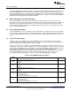
Table 1. TVP5158EVM Jumper Descriptions (continued)
Jumper
Description of Function Default
Designator
Clock source selection
W5 1-2
1-2: Crystal
2-3: Clock from another EVM for cascade mode
I2C EEPROM
W6 ON
ON: Use EEPROM (MUST ALWAYS BE ON)
W7 I2C SCL connection for audio DAC ON
W8 I2C SDA connection for audio DAC ON
I2S input selection for audio DAC
W9 2-3
1-2: TVP5158 mixing output to audio DAC (SD_M)
2-3: TVP5158 record output to audio DAC (SD_R)
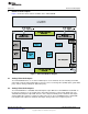
3 System Level Description
The system block diagram illustrated in Figure 2 provides an example of how the TVP5158EVM may be
used for evaluation. Typically, the analog video/audio input is provided by a video source such as a
pattern generator or a DVD player running a test DVD. The TVP5158EVM is configured with the 5-V
supply and the USB cable provided.
The TVP5158EVM analog video output is standard definition component video (YPbPr). These outputs
are then fed into a high-end or studio-quality NTSC/PAL monitor.
The user can also connect the TVP5158EVM to a DaVinci HD EVM and then output combined video from
the DaVinci HD EVM to a 1080i HD monitor.
Figure 2. TVP5158EVM System Level Block Diagram
9
SLEU108–November 2009 TVP5158 Evaluation Module
Submit Documentation Feedback
Copyright © 2009, Texas Instruments Incorporated