MSP-FET430 FLASH Emulation Tool (FET) (For use with IAR Workbench Version 3.
IMPORTANT NOTICE Texas Instruments and its subsidiaries (TI) reserve the right to make changes to their products or to discontinue any product or service without notice, and advise customers to obtain the latest version of relevant information to verify, before placing orders, that information being relied on is current and complete.
U s e r 's July 2004 G u i d e
Preface Read This First About This Manual This manual documents the Texas Instruments MSP-FET430 Flash Emulation Tool (FET). The FET is the program development tool for the MSP430 ultra low power microcontroller. Both available interfaces, the Parallel-Port-Interface and the USB-Interface, are described here. How to Use This Manual Read and follow the Get Started Now! chapter.
Information About Cautions and Warnings This book may contain cautions and warnings. This is an example of a caution statement. A caution statement describes a situation that could potentially damage your software or equipment. CAUTION This is an example of a warning statement. A warning statement describes a situation that could potentially cause harm to you. WARNING The information in a caution or a warning is provided for your protection. Read each caution and warning carefully.
If You Need Assistance Support for the MSP430 device and the FET is provided by the Texas Instruments Product Information Center (PIC). Contact information for the PIC can be found on the TI web site at www.ti.com. Additional devicespecific information can be found on the MSP430 web site at www.ti.com/sc/msp430. Note: Kickstart is supported by Texas Instruments Although Kickstart is a product of IAR, Texas Instruments provides the support for it.
vi
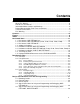
Contents Read This First ................................................................................................................ iii About This Manual .....................................................................................................iii How to Use This Manual ............................................................................................iii Information About Cautions and Warnings ................................................................
Frequently Asked Questions....................................................................................... A-1 A.1 Hardware ........................................................................................................ A-2 A.2 Program Development (Assembler, C-Compiler, Linker)................................. A-3 A.3 Debugging (C-SPY) ........................................................................................ A-5 Hardware........................................................
Figures Figure 3-1. Signal connections for MSP-FET430X110. ...............................................3-5 Figure 3-2. JTAG Signal Connections .........................................................................3-7 Figure A-1. Modification to FET Interface module ..................................................... A-7 Figure B-1. MSP-FET430X110, Schematic.................................................................. B-2 Figure B-2. MSP-FET430X110, PCB Pictorials ...............................
Chapter 1 Get Started Now! This chapter will enable you to inventory your FET, and then it will instruct you to install the software and hardware, and then run the demonstration programs. Topic Page 1.1 Kit Contents, MSP-FET430X110 1-2 1.2 Kit Contents, MSP-FET430Pxx0 (‘P120, ‘P140, ‘P410, ‘P430, ‘P440) 1-2 1.3 Kit Contents, MSP-FET430UIF 1-3 1.4 Software Installation 1-3 1.5 Hardware Installation, MSP-FET430X110 1-3 1.
Get Started Now! 1.1 Kit Contents, MSP-FET430X110 One READ ME FIRST document. One MSP430 CD-ROM. One MSP-FET430X110 Flash Emulation Tool. This is the PCB on which is mounted a 20-pin ZIF socket for the MSP430F11xIDW, MSP430F11x1AIDW, or MSP430F11x2IDW device. A 25-conductor cable originates from the FET. One small box containing two MSP430F1121AIDW device samples. 1.2 Kit Contents, MSP-FET430Pxx0 (‘P120, ‘P140, ‘P410, ‘P430, ‘P440) One READ ME FIRST document. One MSP430 CD-ROM.
Get Started Now! MSP-FET430P430: Eight PCB 1x20 pin headers (Four male and four female). MSP-FET430P440: Eight PCB 1x25 pin headers (Four male and four female). One small box containing two or four MSP430 device samples. MSP-FET430P120: MSP430F123IDW and/or MSP430F1232IDW MSP-FET430P140: MSP430F149IPM and/or MSP430F169IPM MSP-FET430P410: MSP430F413IPM MSP-FET430P430: MSP430F437IPN and/or MSP430FG439 MSP-FET430P440: MSP430F449IPZ Consult the device data sheets for device specifications.
Get Started Now! 1.6 Hardware Installation, MSP-FET430Pxx0 (‘P120, ‘P140, ‘P410, ‘P430, ‘P440) 1) Use the 25-conductor cable to connect the FET Interface module to the parallel port of your PC. 2) Use the 14-conductor cable to connect the FET Interface module to the supplied Target Socket module. 3) Ensure that the MSP430 device is securely seated in the socket, and that its pin 1 (indicated with a circular indentation on the top surface) aligns with the “1” mark on the PCB.
Get Started Now! 3) Click on the tab at the bottom of the workspace window that corresponds to your tool (FETxxx) and desired language (assembler or C). 4) Use PROJECT->OPTIONS->FET Debugger->Setup->Connection to select the appropriate port: LPTx for the parallel FET Interface or TI USB FET for the USB Interface. 5) Use PROJECT->REBUILD ALL to build and link the source code. You can view the source code by double-clicking on the project, and then doubleclicking on the displayed source file.
Get Started Now! 1.9 Important MSP430 Documents on the CD-ROM and WEB The primary sources of MSP430 information are the device specific data sheet and User’s Guide. The most up to date versions of these documents available at the time of production have been provided on the CD-ROM included with this tool. The MSP430 web site (www.ti.com/sc/msp430) will contain the latest version of these documents.
Chapter 2 Development Flow This chapter discusses how to use Kickstart to develop your application software, and how to use C-SPY to debug it. Topic Page 2.1 Overview 2-2 2.2 Using Kickstart 2-2 2.2.1 Project Settings 2-3 2.2.2 Creating a Project from Scratch 2-5 2.2.3 Using an Existing IAR V1.x/V2.x Project 2-6 2.2.4 Stack Management within the .xcl Files 2-6 2.2.5 How to Generate Texas Instrument .TXT (and other format) Files 2-7 2.2.6 Overview of Example Programs 2-7 2.
Development Flow 2.1 Overview Applications are developed in assembler and/or C using the Workbench, and they are debugged using C-SPY. C-SPY is seamlessly integrated into the Workbench. However, it is more convenient to make the distinction between the code development environment (Workbench) and the debugger (C-SPY). CSPY can be configured to operate with the FET (i.e., an actual MSP430 device), or with a software simulation of the device.
Development Flow The simulator will input a maximum of 4K bytes of code. A “Full” (i.e., unrestricted) version of the software tools can be purchased from IAR. A mid-featured tool set – called “Baseline”, with a 12K byte C code size limitation and basic floating-point operations – is also available from IAR. Consult the IAR web site (www.iar.se) for more information. 2.2.1 Project Settings The settings required to configure the Workbench and C-SPY are numerous and detailed.
Development Flow Enable the Device Description file. This file makes C-SPY “aware” of the specifics of the device it is debugging.
Development Flow Note: Avoid the use of absolute pathnames when referencing files. Instead, use the relative pathname keywords $TOOLKIT_DIR$ and $PROJ_DIR$. Refer to the IAR documentation for a description of these keywords. The use of relative pathnames will permit projects to be moved easily, and projects will not require modification when IAR systems are upgraded (say, from Kickstart, or Baseline, to Full). 2.2.
Development Flow Note: How to add assembler source files to your project The default file type presented in the Add Files window is “C/C++ Files”. In order to view assembler files (.s43), select “Assembler Files” in the “Files of type” drop-down menu. 8) Configure the project options (PROJECT->OPTIONS).
Development Flow system stack within C programs. CSTACK can also be used in assembler programs [MOV #SFE(CSTACK), SP]. CSTACK is defined to extend from the last location of RAM for 50 bytes (i.e., the stack extends downwards through RAM for 50 bytes). Other statements in the .xcl file define other relocatable regions that are allocated from the first location of RAM to the bottom of the stack. It is critical to note that: 1. The supplied .
Development Flow Note: Some example programs require a 32KHz crystal on LFXT1, and not all FETs are supplied with a 32KHz crystal.
Development Flow 2.3 Using C-SPY Refer to Appendix C for a description of FET-specific menus within C-SPY. 2.3.1 Breakpoint Types The C-SPY breakpoint mechanism makes use of a limited number of on-chip debugging resources (specifically, N breakpoint registers, refer to Table 2-1 below). When N or fewer breakpoints are set, the application runs at full device speed (or “Realtime”).
Development Flow The RUN TO CURSOR operation temporarily requires a breakpoint. Consequently, only N-1 breakpoints can be active when RUN TO CURSOR is used if virtual breakpoints are disabled. Refer to FAQ, Debugging #31). If, while processing a breakpoint, an interrupt becomes active, C-SPY will stop at the first instruction of the interrupt service routine. Refer to FAQ, Debugging #24). 2.3.
Development Flow 2.3.4 Using Watch Windows The C-SPY Watch Window mechanism permits C variables to be monitored during the debugging session. Although not originally designed to do so, the Watch Window mechanism can be extended to monitor assembler variables.
Chapter 3 Design Considerations for In-Circuit Programming This chapter presents signal requirements for in-circuit programming of the MSP430. Topic Page 3.1 Bootstrap Loader 3-2 3.2 External Power 3-2 3.3 Device Signals 3-3 3.4 Signal Connections for In-System Programming and Debugging, MSP-FET430X110 3-4 3.
Design Considerations for In-Circuit Programming 3.1 Bootstrap Loader The JTAG pins provide access to the Flash memory of the MSP430F device. On some devices, these pins must be “shared” with the device port pins, and this sharing of pins can complicate a design (or it may simply not be possible to do so). As an alternative to using the JTAG pins, MSP430F devices contain a program (a “Bootstrap Loader”) that permits the Flash memory to be erased and programmed simply, using a reduced set of signals.
Design Considerations for In-Circuit Programming levels accordingly). Again, refer to the Target Socket module schematic in Appendix B.
Design Considerations for In-Circuit Programming 3.3 Device Signals The following device signals should be brought out (i.e., made accessible) so that the FET, GANG430, and PRGS430 tools can be utilized: RST/NMI ❏ TMS ❏ TCK ❏ TDI ❏ TDO ❏ GND ❏ VCC ❏ TEST† Notes: Design considerations to support the FET, GANG430, and PRGS430 1) Connections to XIN and XOUT are not required, and should not be made. 2) PRGS430 software Version 1.10 or greater must be used.
Design Considerations for In-Circuit Programming 3.4 Signal Connections for In-System Programming and Debugging, MSPFET430X110 With the proper connections, you can use the C-SPY debugger and the MSPFET430X110 to program and debug code on your own target board. In addition, the connections will support the GANG430 and PRGS430, thus providing an easy way to program prototype boards, if desired.
Design Considerations for In-Circuit Programming Disconnect if target has it's own 'local' power source VCC 100nF 10uF 100K VCC/AV CC/DVCC** RST/NMI VCC Test 2 1 4 3 6 5 8 7 10 9 12 11 TDO/TDI TDI TDO/TDI TDI TMS TMS TCK TCK GND MSP430 RST/NMI 14 13 14 pos. header (3M p/n 2514-6002) (Digi-Key p/n MHB14K-ND) Test 20K *** VSS/AVSS/DVSS** * Not present on all devices ** Pins vary by device. *** Pulldown not required on all devices. Check device datasheet pin description.
Design Considerations for In-Circuit Programming 3.5 Signal Connections for In-System Programming and Debugging, MSPFETP430IF, MSP-FET430UIF With the proper connections, you can use the C-SPY debugger and an FET hardware JTAG interface such as the MSP-FETP430IF and MSP-FET430UIF to program and debug code on your own target board. In addition, the connections will support the GANG430 or PRGS430, thus providing an easy way to program prototype boards, if desired.
Design Considerations for In-Circuit Programming Connect if target has it's own 'local' power source VCC 100nF Connect to power target from FET or GANG430 if not using a local power source 100K 10uF VCC/AVCC/DVCC** RST/NMI VCC(FromTool) VCC(Local Sense) Test 2 1 4 3 6 5 8 7 10 9 12 11 TDO/TDI TDI TDO/TDI TDI TMS TMS TCK TCK GND MSP430 RST/NMI 14 13 14 pos. header (3M p/n 2514-6002) (Digi-Key p/n MHB14K-ND) Test 20K*** VSS/AVSS/DVSS** *** Pulldown not required on all devices.
Appendix A Frequently Asked Questions This appendix presents solutions to frequently asked questions regarding hardware, program development, and debugging tools. Topic Page A.1 Hardware A-2 A.2 Program Development (Assembler, C-Compiler, Linker) A-3 A.
Frequently Asked Questions A.1 Hardware 1) The state of the device (CPU registers, RAM memory, etc.) is undefined following a reset. Exceptions to the above statement are that the PC is loaded with the word at 0xfffe (i.e., the reset vector), the status register is cleared, and the peripheral registers (SFRs) are initialized as documented in the device Family User’s Guides. C-SPY resets the device after programming it.
Frequently Asked Questions low power mode is restored (using GO). This behavior appears to happen on all devices except the MSP430F12x. 12) The following ZIF sockets are used in the FET tools and Target Socket modules: 20-pin device (DW package): Wells-CTI 652 D020 ❏ 28-pin device (DW package): Wells-CTI 652 D028 ❏ 64-pin device (PM package): Yamaichi IC51-0644-807 ❏ 80-pin device (PN package): Yamaichi IC201-0804-014 ❏ 100-pin device (PZ package): Yamaichi IC201-1004-008 Wells-CTI: http://www.wellscti.
Frequently Asked Questions 9) It is possible to mix assembler and C programs within the Workbench. Refer to the Assembler Language Interface chapter of the C/C++ Compiler Reference Guide from IAR. 10) The Workbench can produce an object file in Texas Instruments .TXT format. C-SPY cannot input an object file in Texas Instruments .TXT format. 11) The example programs giving in the Kickstart documentation (i.e., Demo, Tutor, etc.) are not correct. The programs will work only in the simulator.
Frequently Asked Questions Optimization: NONE is supported within PROJECT->OPTIONS>C/C++ COMPILER->CODE->OPTIMIZATIONS. Alternatively, variables can be declared volatile. 16) The IAR Tutorial assumes a Full or Baseline version of the Workbench. Within a Kickstart system, it is not possible to configure the C compiler to output assembler mnemonics. 17) Existing projects from an IAR 1.x system can be used within the new IAR 2.x/3.x system; refer to the IAR document Migration guide for EW430 x.x.
Frequently Asked Questions software can prevent the C-SPY/FET driver from accessing the parallel port, and, hence, communicating with the device. It may be necessary to reboot the computer to complete the installation of the required parallel port drivers. Revisions 1.0, 1.1, and 1.2 of the FET Interface module require a hardware modification; a 0.1uF capacitor needs to be installed between U1 pin 1 (signal VCC_MSP) and ground.
Frequently Asked Questions For revisions 1.0, 1.1, and 1.2 of the FET Interface module, install a 0.1uF capacitor between the indicated points (pins 4 and 5 of U1). 0.1u Figure A-1.
Frequently Asked Questions 2) C-SPY can download data into RAM, INFORMATION, and Flash MAIN memories. A warning message is output if an attempt is made to download data outside of the device memory spaces. 3) C-SPY can debug applications that utilize interrupts and low power modes. Refer to FAQ, Debugging #24). 4) C-SPY cannot access the device registers and memory while the device is running. C-SPY will display “-“ to indicate that a register/memory field is invalid.
Frequently Asked Questions the JTAG pins and the measurements will be erroneous. Refer to FAQ, Debugging #12) and Hardware #11). 11) Most C-SPY settings (breakpoints, etc.) are now preserved between sessions. 12) When C-SPY has control of the device, the CPU is ON (i.e., it is not in low power mode) regardless of the settings of the low power mode bits in the status register. Any low power mode conditions will be restored prior to STEP or GO.
Frequently Asked Questions (RESYNCHRONIZE JTAG)) and before C-SPY has regained control of the device that the device will execute normally. This behavior may have side effects. Once C-SPY has regained control of the device, it will perform a reset of the device and retain control. 19) When programming the Flash, do not set a breakpoint on the instruction immediately following the write to Flash operation.
Frequently Asked Questions 26) On devices equipped with a Data Transfer Controller (DTC), the completion of a data transfer cycle will preempt a single step of a low power mode instruction. The device will advance beyond the low power mode instruction only after an interrupt is processed. Until an interrupt is processed, it will appear that the single step has no effect.
Frequently Asked Questions 35) Special Function Registers (SFRs) – or the peripheral registers – are now displayed in VIEW->REGISTER; there is no longer an SFR Window. 36) The putchar()/getchar() breakpoints are set only if these functions are present (and the mechanism is enabled). Note that putchar()/getchar() could be indirectly referenced by a library function. 37) The Flash program/download progress bar does not update gradually. This behavior is to be expected.
Appendix B Hardware This appendix contains information relating to the FET hardware, including schematics and PCB pictorials. Topic Page Figure B-1. MSP-FET430X110, Schematic B-2 Figure B-2. MSP-FET430X110, PCB Pictorials B-3 Figure B-3. MSP-FET430IF FET Interface module, Schematic B-4 Figure B-4. MSP-FET430IF FET Interface module, PCB Pictorial B-5 Figure B-5. MSP-TS430DW28 Target Socket module, Schematic B-6 Figure B-6. MSP-TS430DW28 Target Socket module, PCB Pictorials B-7 Figure B-7.
Hardware Figure B-1.
Hardware Connector J4 External power connector LED connected to P1.0 Jumper J5 Open to disconnect LED R6 Ensure value is 82 ohms Orient Pin 1 of MSP430 device Jumper J1 Open to measure current P2.1 P2.2 RST P2.0 J2 XOUT XIN P2.5 Vss TST Vcc P2.4 P2.3 P1.1 P1.0 J3 P1.3 P1.2 P1.5 P1.4 P1.7 P1.6 Figure B-2.
Hardware Figure B-3.
Hardware R6 Ensure value is 82 ohms Figure B-4.
Hardware Note: Connections between the JTAG header and pins XOUT and XIN are no longer required, and should not be made. Figure B-5.
Hardware LED connected to P1.0 Jumper J4 Open to disconnect LED Jumper J5 Open to measure current Connector J3 External power connector Remove R8 and jumper R9 Orient Pin 1 of MSP430 device Figure B-6.
Hardware Note: Connections between the JTAG header and pins XOUT and XIN are no longer required, and should not be made. Figure B-7. MSP-TS430PM64 Target Socket module, Schematic, Rev. 1.
Hardware Jumper J6 Open to disconnect LED Orient Pin 1 of MSP430 device Jumper J7 Open to measure current LED connected to pin 12 Connector J5 External power connector Remove R8 and jumper R9 Figure B-8. MSP-TS430PM64 Target Socket module, PCB Pictorials, Rev. 1.
Hardware Note: Connections between the JTAG header and pins XOUT and XIN are no longer required, and should not be made. Figure B-9. MSP-TS430PM64 Target Socket module, Schematic, Rev. 1.
Hardware LED connected to pin 12 Jumper J7 Open to measure current Connector J5 External power connection Remove R8 and jumper R9 Jumper J6 Open to disconnect LED Orient Pin 1 of MSP430 device Figure B-10. MSP-TS430PM64 Target Socket module, PCB Pictorials, Rev. 1.
Hardware B.1 History of changes to MSP-TS430PM64 Target Socket module Changes from Rev. 0.1 to 1.0: Connector J5 for external power was added Connectors FETJ2 and FETJ3 were removed C8 was changed from 100nF to 10nF R5 was changed from 100k to 47k R13 and R14 were added to support BSL usage on F413. They are not assembled R4 was removed Changes from Rev. 1.0 to 1.1: Connection JTAG/6 <-> J1/9: R4=0Ohm was inserted. R4 is not assembled. This isolates XOUT from the JTAG connector. On Rev. 0.
Hardware Figure B-11.
Hardware Jumper J7 Open to measure current LED connected to pin 12 Jumper J6 Open to disconnect LED Connector J5 External power connection Remove R8 and jumper R9 Orient Pin 1 of MSP430 device Figure B-12.
Hardware Note: Connections between the JTAG header and pins XOUT and XIN are no longer required, and should not be made. Figure B-13.
Hardware Jumper J6 Open to disconnect LED Jumper J7 Open to measure current LED connected to pin 12 Connector J5 External power connection Remove R8 and jumper R9 Orient Pin 1 of MSP430 device Figure B-14.
Hardware Figure B-15.
Hardware B-18
Hardware B-19
Hardware B-20
Hardware B-21
Appendix C FET Specific Menus This appendix describes the C-SPY menus that are specific to the FET. Topic Page C.1 EMULATOR C-2 C.1.1 EMULATOR->RELEASE JTAG ON GO C-2 C.1.2 EMULATOR->RESYNCHRONIZE JTAG C-2 C.1.3 EMULATOR->INIT NEW DEVICE C-2 C.1.4 EMULATOR->SHOW USED BREAKPOINTS C-2 C.1.5 EMULATOR->ADVANCED->GENERAL CLOCK CONTROL C-2 C.1.6 EMULATOR->ADVANCED->EMULATION MODE C-2 C.1.7 EMULATOR->ADVANCED->MEMORY DUMP C-3 C.1.8 EMULATOR->ADVANCED->BREAKPOINT COMBINER C-3 C.1.
FET Specific Menus C.1 EMULATOR The current device type is displayed. C.1.1 EMULATOR->RELEASE JTAG ON GO C-SPY uses the device JTAG signals to debug the device. On some MSP430 devices, these JTAG signals are shared with the device port pins. Normally, CSPY maintains the pins in JTAG mode so that the device can be debugged. During this time the port functionality of the shared pins is not available.
FET Specific Menus Refer to Appendix D. C.1.7 EMULATOR->ADVANCED->MEMORY DUMP Write the specified device memory contents to a specified file. A conventional dialog is displayed that permits the user to specify a file name, a memory starting address, and a length. The addressed memory is then written in a text format to the named file. Options permit the user to select word or byte text format, and address information and register contents can also be appended to the file. C.1.
FET Specific Menus C.1.14 EMULATOR->GIE on/off Enables or disables all interrupts. Needs to be restored manually before GO. C.1.15 EMULATOR->LEAVE TARGET RUNNING If C-SPY is closed, the target keeps running the user program. C.1.16 EMULATOR->FORCE SINGLE STEPPING On GO the program is executed by single steps. Only in this mode the cycle counter works correctly. C.1.17 EMULATOR->SET VCC On the USB FET the target supply voltage can be adjusted between 1.8V and 5.0V.
Appendix D 80-pin MSP430F44x and MSP430F43x Device Emulation 80-pin MSP430F44x and MSP430F43x devices can be emulated by the 100-pin MSP430F449 device. Table D-1. F4xx/80-pin Signal Mapping lists where the pin signals of an 80pin device appear on the pins of an MSP-TS430PZ100 Target Socket module. Note: The MSP-TS430PZ100 must be modified as indicated. Refer to Appendix C.1.6 EMULATOR->ADVANCED->EMULATION MODE to enable the emulation mode.
80-pin MSP430F44x and MSP430F43x Device Emulation Table D-1. F4xx/80-pin Signal Mapping D-2 F4xx/80-pin Signal F4xx/80-pin Pin Number MSP430TS430PZ100 Pin Number DVcc1 P6.3/A3 P6.4/A4 P6.5/A5 P6.6/A6 P6.7/A7 VREF+ XIN XOUT VeREF+ VREF-/VeREFP5.1/S0 P5.0/S1 P4.7/S2 P4.6/S3 P4.5/S4 P4.4/S5 P4.3/S6 P4.2/S7 P4.1/S8 P4.0/S9 S10 S11 S12 S13 S14 S15 S16 S17 P2.7/ADC12CLK/S18 P2.6/CAOUT/S19 S20 S21 S22 S23 P3.7/S24 P3.6/S25 P3.5/S24 P3.4/S27 P3.3/UCLK0/S28 P3.2/SOMI0/S29 P3.1/SIMO0/S30 P3.0/STE0/S31 COM0 P5.
80-pin MSP430F44x and MSP430F43x Device Emulation P5.5/R13 P5.6/R23 P5.7/R33 DVcc2 DVss2 P2.5/URXD0 P2.4/UTXD0 P2.3.TB2 P2.2/TB1 P2.1/TB0 P2.0/TA2 P1.7/CA1 P1.6/CA0 P1.5/TACLK/ACLK P1.4/TBCLK/SMCLK P1.3/TBOUTH/SVSOUT P1.2/TA1 P1.1/TA0/MCLK P1.0/TA0 XT2OUT XT2IN TDO/TDI TDI TMS TCK RST/NMI P6.0/A0 P6.1/A1 P6.
Appendix E TI to IAR 2.x/3.x Assembler Migration Texas Instruments made a suite of development tools for the MSP430, including a comprehensive assembler and device simulator. The source of the TI assembler and the source of the Kickstart assembler are not 100% compatible; the instruction mnemonics are identical, while the assembler directives are somewhat different. The following section documents the differences between the TI assembler directives and the Kickstart 2.x/3.x assembler directives.
TI to IAR 2.x/3.x Assembler Migration E.1 Segment Control RSEG defines a Relocatable SEGment. A relocatable segment means that the code that follows the RSEG statement will be place *somewhere* in the region defined for that segment (in the .xcl file). In other words, the code can be "relocated", and you don't know (or care) where it's put. In the .xcl files provided with the FET, multiple segments are defined in the same memory regions. ASEG defines an Absolute SEGment.
TI to IAR 2.x/3.x Assembler Migration consecutive backslashes (\\). In Asm430 syntax, a quote is represented by two consecutive quotes (“”). See examples below: Character String PLAN “C” \dos\command.com Concatenated string (i.e. Error 41) E.2.3 Asm430 Syntax (TI) “PLAN “”C””” “\dos\command.com” - A430 Syntax (IAR) “PLAN \”C\”” “\\dos\\command.com” “Error ” “41” Section Control Directives Asm430 has three predefined sections into which various parts of a program are assembled.
TI to IAR 2.x/3.x Assembler Migration E.2.4 Constant Initialization Directives Description Asm430 Directive (TI) A430 Directive (IAR) Initialize one or more successive bytes or .byte or .string DB text strings Initialize a 48-bit MSP430 floating-point .double 1) constant Initialize a variable-length field .field 2) Initialize a 32-bit MSP430 floating-point .float DF 3) constant Reserve size bytes in the current section .space DS Initialize one or more text strings .
TI to IAR 2.x/3.x Assembler Migration E.2.6 File Reference Directives Description Asm430 Directive (TI) A430 Directive (IAR) Include source statements from another .copy or .include #include or $ file Identify one or more symbols that are .def PUBLIC or EXPORT defined in the current module and used in other modules Identify one or more global (external) .global 1) symbols Define a macro library .mlib 2) Identify one or more symbols that are .
TI to IAR 2.x/3.x Assembler Migration X SET ENDR ENDM X+1 ; Increment counter Additional A430 Directives (IAR) Repeatable block assembly: Formal argument is substituted by each character of a string. Repeatable block assembly: formal argument is substituted by each string of a list of actual arguments. See also Preprocessor Directives E.2.8 A430 Directive (IAR) REPTC REPTI Symbol Control Directives The scope of assembly-time symbols differs in the two assemblers.
TI to IAR 2.x/3.x Assembler Migration E.2.9 Macro Directives Description Define a macro Exit prematurely from a macro End macro definition Asm430 Directive (TI) .macro .mexit .endm Additional A430 Directives (IAR) Create symbol, local to a macro 1) In Asm430 local symbols are suffixed by a question mark (?). E.2.
TI to IAR 2.x/3.x Assembler Migration Additional A430 Directives (IAR) Assign a value to a preprocessor symbol Undefine a preprocessor symbol Conditional assembly Assemble if a preprocessor symbol is defined (not defined) End a #if, #ifdef or #ifndef block Includes a file Generate an error E.2.12 Alphabetical Listing and Cross Reference of Asm430 Directives Asm430 directive .align .asg .break .bss .byte or .string .copy or .include .data .def .double .else .elseif .emsg .end .endif .endloop .endm .
TI to IAR 2.x/3.
Appendix F MSP-FET430UIF Installation Guide This section describes the hardware installation process of the MSPFET430UIF USB debug interface on a PC running Windows XP. The installation procedure for a Windows 2000 system is very similar and therefore not shown here. Topic F.
MSP-FET430UIF Installation Guide F.1 Hardware Installation 1) Connect the MSP-FET430UIF USB Debug Interface with a USB cable to a USB port of your PC 2) Windows now should recognize the new hardware as an “MSP430 USB FET x.xx.xx” (Figure F-1). Figure F-1. WinXP Hardware Recognition 3) The Hardware Wizard should start automatically and popup the “Found New Hardware Wizard” dialog window. 4) Instruct the Wizard to install the hardware driver from a specific location (Figure F-2). Figure F-2.
MSP-FET430UIF Installation Guide Figure F-3. WinXP Driver Location Selection Folder 6) The Wizard should generate a message that an appropriate driver has been found. 7) Note that WinXP shows a warning that the driver is not certified by Microsoft. Ignore this warning and click “Continue Anyway” (Figure F-4).
MSP-FET430UIF Installation Guide Figure F-4. WinXP Driver Installation 8) In the next step the Wizard installs the driver files. 9) The Wizard now shows a message that it has finished the installation of the software for “MSP430 USB FET Adapter”. 10) After closing the Hardware Wizard, Windows automatically recognizes another new hardware device called “Texas Instruments UMP Serial Port”.
MSP-FET430UIF Installation Guide Figure F-5.