
User's Manual

System Reset and Initialization
2-6 System Resets, Interrupts, and Operating Modes
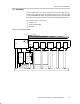
2.2.1 (Non)-Maskable Interrupts (NMI)
(Non)-maskable NMI interrupts are not masked by the general interrupt enable
bit (GIE), but are enabled by individual interrupt enable bits (ACCVIE, NMIIE,
OFIE). When a NMI interrupt is accepted, all NMI interrupt enable bits are
automatically reset. Program execution begins at the address stored in the
(non)-maskable interrupt vector, 0FFFCh. User software must set the required
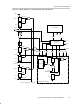
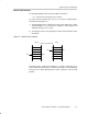
NMI interrupt enable bits for the interrupt to be re-enabled. The block diagram
for NMI sources is shown in Figure 2−4.
A (non)-maskable NMI interrupt can be generated by three sources:
- An edge on the RST/NMI pin when configured in NMI mode
- An oscillator fault occurs
- An access violation to the flash memory
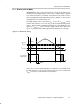
Reset/NMI Pin
At power-up, the RST/NMI pin is configured in the reset mode. The function
of the RST/NMI pins is selected in the watchdog control register WDTCTL. If
the RST/NMI pin is set to the reset function, the CPU is held in the reset state
as long as the RST/NMI pin is held low. After the input changes to a high state,
the CPU starts program execution at the word address stored in the reset
vector, 0FFFEh.
If the RST/NMI pin is configured by user software to the NMI function, a signal
edge selected by the WDTNMIES bit generates an NMI interrupt if the NMIIE
bit is set. The RST/NMI flag NMIIFG is also set.
Note: Holding RST/NMI Low
When configured in the NMI mode, a signal generating an NMI event should
not hold the RST/NMI pin low. If a PUC occurs from a different source while
the NMI signal is low, the device will be held in the reset state because a PUC
changes the RST/NMI pin to the reset function.
Note: Modifying WDTNMIES
When NMI mode is selected and the WDTNMIES bit is changed, an NMI can
be generated, depending on the actual level at the RST/NMI pin. When the
NMI edge select bit is changed before selecting the NMI mode, no NMI is
generated.