
User's Manual

USART Operation: UART Mode
14-12 USART Peripheral Interface, UART Mode
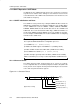
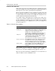
Baud Rate Bit Timing
The first stage of the baud rate generator is the 16-bit counter and comparator.
At the beginning of each bit transmitted or received, the counter is loaded with
INT(N/2) where N is the value stored in the combination of UxBR0 and UxBR1.
The counter reloads INT(N/2) for each bit period half-cycle, giving a total bit
period of N BRCLKs. For a given BRCLK clock source, the baud rate used
determines the required division factor N:
N =
BRCLK
baud rate
The division factor N is often a non-integer value of which the integer portion
can be realized by the prescaler/divider. The second stage of the baud rate
generator, the modulator, is used to meet the fractional part as closely as
possible. The factor N is then defined as:
N + UxBR )
1
n
S
n*1
i+0
m
i
Where:
N: Target division factor
UxBR: 16-bit representation of registers UxBR0 and UxBR1
i: Bit position in the character
n: Total number of bits in the character
m
i
: Data of each corresponding modulation bit (1 or 0)
Baud rate +
BRCLK
N
+
BRCLK
UxBR )
1
n
ȍ
n–1
i+0
m
i
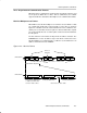
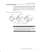
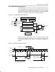
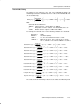
The BITCLK can be adjusted from bit to bit with the modulator to meet timing
requirements when a non-integer divisor is needed. Timing of each bit is
expanded by one BRCLK clock cycle if the modulator bit m
i
is set. Each time
a bit is received or transmitted, the next bit in the modulation control register
determines the timing for that bit. A set modulation bit increases the division
factor by one while a cleared modulation bit maintains the division factor given
by UxBR.
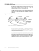
The timing for the start bit is determined by UxBR plus m0, the next bit is
determined by UxBR plus m1, and so on. The modulation sequence begins
with the LSB. When the character is greater than 8 bits, the modulation
sequence restarts with m0 and continues until all bits are processed.
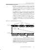
Determining the Modulation Value
Determining the modulation value is an interactive process. Using the timing
error formula provided, beginning with the start bit , the individual bit errors are
calculated with the corresponding modulator bit set and cleared. The
modulation bit setting with the lower error is selected and the next bit error is
calculated. This process is continued until all bit errors are minimized. When
a character contains more than 8 bits, the modulation bits repeat. For example,
the 9th bit of a character uses modulation bit 0.