
User's Manual

System Reset and Initialization
2-10 System Resets, Interrupts, and Operating Modes
Each individual peripheral interrupt is discussed in the associated peripheral
module chapter in this manual.
2.2.3 Interrupt Processing
When an interrupt is requested from a peripheral and the peripheral interrupt
enable bit and GIE bit are set, the interrupt service routine is requested. Only
the individual enable bit must be set for (non)-maskable interrupts to be
requested.
Interrupt Acceptance
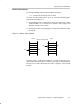
The interrupt latency is 6 cycles, starting with the acceptance of an interrupt
request, and lasting until the start of execution of the first instruction of the
interrupt-service routine, as shown in Figure 2−6. The interrupt logic executes
the following:
1) Any currently executing instruction is completed.
2) The PC, which points to the next instruction, is pushed onto the stack.
3) The SR is pushed onto the stack.
4) The interrupt with the highest priority is selected if multiple interrupts
occurred during the last instruction and are pending for service.
5) The interrupt request flag resets automatically on single-source flags.
Multiple source flags remain set for servicing by software.
6) The SR is cleared with the exception of SCG0, which is left unchanged.
This terminates any low-power mode. Because the GIE bit is cleared,
further interrupts are disabled.
7) The content of the interrupt vector is loaded into the PC: the program
continues with the interrupt service routine at that address.
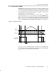
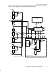
Figure 2−6. Interrupt Processing
Item1
Item2
SP TOS
Item1
Item2
SP TOS
PC
SR
Before
Interrupt
After
Interrupt