
User's Manual


LCD Controller Operation
18-7LCD Controller
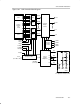
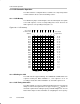
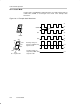
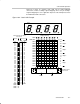
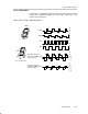
Figure 18−4 shows an example static LCD, pin-out, LCD-to-MSP430
connections, and the resulting segment mapping. This is only an example.
Segment mapping in a user’s application depends on the LCD pin-out and on
the MSP430-to-LCD connections.
Figure 18−4. Static LCD Example
A
B
G
0
3
Sn+1 Sn
Parallel-Serial
Conversion
c
28
26
-- b a
32103210
COM
091h
---- ------
-- d c---- ------
-- f e---- ------
-- h g---- ------
-- b a---- ------
-- d c---- ------
-- f e---- ------
-- h g---- ------
-- b a---- ------
-- d c---- ------
-- f e---- ------
-- h g---- ------
-- b a---- ------
-- d---- ------
-- f e---- ------
092h
093h
094h
095h
096h
097h
098h
099h
09Ah
09Bh
09Ch
09Dh
09Eh
09Fh
24
22
20
18
16
14
12
10
8
6
4
2
0
Digit 4
Digit 3
Digit 2
Digit 1
a
b
c
d
e
f
g
h
a
b
c
d
e
f
g
h
a
b
c
d
e
f
g
h
a
b
c
d
e
f
g
h
S0
S1
S2
S3
S4
S5
S6
S7
S8
S9
S10
S11
S12
S13
S14
S15
S16
S17
S18
S19
S20
S21
S22
S23
S24
S25
S26
S27
S28
S29
S30
S31
COM0
COM1
COM2
COM3
1
2
3
4
5
6
7
8
9
10
11
12
13
14
15
16
17
18
19
20
21
22
23
24
25
26
27
28
29
30
31
32
33
1a
1b
1c
1d
1e
1f
1g
1h
2a
2b
2c
2d
2e
2f
2g
2h
3a
3b
3c
3d
3e
3f
3g
3h
4a
4b
4c
4d
4e
4f
4g
4h
COM0
PIN COM0
’430 Pins LCD Pinout
NC
NC
NC
Pinout and Connections
LCD
Display Memory
Connections
A
B
G
0
3
32100321
-- h g---- ------
n = 30
MAB 0A0h