
User's Manual


www.ti.com
PRODUCT PREVIEW
7.8.1 PLL2 Controller Device-Specific Information
TMS320C6454
Fixed-Point Digital Signal Processor
SPRS311A – APRIL 2006 – REVISED DECEMBER 2006
7.8.1.1 Internal Clocks and Maximum Operating Frequencies
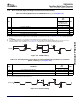
As shown in Figure 7-23 , the output of PLL2, PLLOUT, is divided by 2 and directly fed to the DDR2
memory controller. This clock is used by the DDR2 memory controller to generate DDR2CLKOUT and
DDR2CLKOUT. Note that, internally, the data bus interface of the DDR2 memory controller is clocked by
SYSCLK2 of the PLL1 controller.
The PLLOUT/2 clock is also fed back into the PLL2 controller where it becomes SYSREFCLK. Divider D1
of the PLL2 controller generates SYSCLK1 for the Ethernet media access controller (EMAC). The EMAC
uses SYSCLK1 to generate the necessary clock for each of its interfaces. Divider D1 should be
programmed to ÷2 mode [default] when using the Gigabit Media Independent Interface (GMII) mode and
to ÷5 mode when using the Reduce Gigabit Media Independent Interface (RGMII). Divider D1 is software
programmable and, if necessary, must be programmed after device reset to ÷5 when the RGMII mode of
the EMAC is used. Note that, internally, the data bus interface of the EMAC is clocked by SYSCLK3 of the
PLL2 controller.
Note that there is a minimum and maximum operating frequency for PLLREF, PLLOUT, and SYSCLK1.
The clock generator must not be configured to exceed any of these constraints. For the PLL clocks input
and output frequency ranges, see Table 7-31 . Also, when EMAC is enabled with RGMII or GMII, CLKIN2
must be 25 MHz.
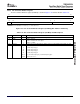
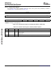
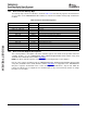
Table 7-31. PLL2 Clock Frequency Ranges
CLOCK SIGNAL MIN MAX UNIT
PLLREF (PLLEN = 1) 12.5 26.7 MHz
PLLOUT 250 533 MHz
SYSCLK1
(1)
50 125 MHz
(1) SYSCLK1 restriction applies only when the EMAC is enabled and the RGMII or GMII modes are used. SYSCLK1 must be programmed
to 125 MHz when the GMII mode is used and to 50 MHz when the RGMII mode is used.
7.8.1.2 PLL2 Controller Operating Modes
Unlike the PLL1 controller which can operate in bypass and a PLL mode, the PLL2 controller only
operates in PLL mode. In this mode, SYSREFCLK is generated outside the PLL2 controller by dividing the
output of PLL2 by two.
The PLL2 controller is affected by power-on reset and warm reset. During these resets the PLL2 controller
registers get reset to their default values. The internal clocks of the PLL2 controller are also affected as
described in Section 7.6 , Reset Controller.
PLL2 is only unlocked during the power-up sequence (see Section 7.6 , Reset Controller ) and is locked by
the time the RESETSTAT pin goes high. It does not lose lock during any of the other resets.
Submit Documentation Feedback C64x+ Peripheral Information and Electrical Specifications 139