
User's Manual


www.ti.com
PRODUCT PREVIEW
7.4 Enhanced Direct Memory Access (EDMA3) Controller
7.4.1 EDMA3 Device-Specific Information
TMS320C6454
Fixed-Point Digital Signal Processor
SPRS311A – APRIL 2006 – REVISED DECEMBER 2006
The primary purpose of the EDMA3 is to service user-programmed data transfers between two
memory-mapped slave endpoints on the device. The EDMA3 services software-driven paging transfers
(e.g., data movement between external memory and internal memory), performs sorting or subframe
extraction of various data structures, services event driven peripherals such as the McBSP, and offloads
data transfers from the device CPU.
The EDMA3 includes the following features:
• Fully orthogonal transfer description
– 3 transfer dimensions: array (multiple bytes), frame (multiple arrays), and block (multiple frames)
– Single event can trigger transfer of array, frame, or entire block
– Independent indexes on source and destination
• Flexible transfer definition:
– Increment or FIFO transfer addressing modes
– Linking mechanism allows for ping-pong buffering, circular buffering, and repetitive/continuous
transfers, all with no CPU intervention
– Chaining allows multiple transfers to execute with one event
• 256 PaRAM entries
– Used to define transfer context for channels
– Each PaRAM entry can be used as a DMA entry, QDMA entry, or link entry
• 64 DMA channels
– Manually triggered (CPU writes to channel controller register), external event triggered, and chain
triggered (completion of one transfer triggers another)
• 8 Quick DMA (QDMA) channels
– Used for software-driven transfers
– Triggered upon writing to a single PaRAM set entry
• 4 transfer controllers/event queues with programmable system-level priority
• Interrupt generation for transfer completion and error conditions
• Memory protection support
– Active memory protection for accesses to PaRAM and registers
• Debug visibility
– Queue watermarking/threshold allows detection of maximum usage of event queues
– Error and status recording to facilitate debug
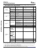
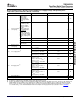
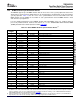
Each of the transfer controllers has a direct connection to the switched central resource (SCR). Table 4-1
lists the peripherals that can be accessed by the transfer controllers.
A DSP interrupt must be generated at the end of an HPI or PCI boot operation to begin execution of the
loaded application. Since the DSP interrupt generated by the HPI and PCI is mapped to the EDMA event
DSP_EVT (DMA channel 0), it will get recorded in bit 0 of the EDMA Event Register (ER). This event must
be cleared by software before triggering transfers on DMA channel 0. The EDMA3 on the C6454 DSP
supports active memory protection, but it does not support proxied memory protection.
The EDMA supports two addressing modes: constant addressing and increment addressing mode. On the
C6454 DSP, constant addressing mode is not supported by any peripheral or internal memory. For more
information on these two addressing modes, see the TMS320C645x DSP Enhanced DMA (EDMA)
Controller User's Guide (literature number SPRU966 ).
C64x+ Peripheral Information and Electrical Specifications98 Submit Documentation Feedback