TMS320DM643x DMP DSP Subsystem Reference Guide Literature Number: SPRU978E March 2008
SPRU978E – March 2008 Submit Documentation Feedback
Contents Preface ............................................................................................................................... 9 1 Introduction Introduction ......................................................................................................... 12 1.2 Block Diagram ..................................................................................................... 12 1.3 DSP Subsystem in TMS320DM643x DMP 1.3.1 2 ...................................................
5.3.2 5.4 Steps for Changing PLL2 Frequency .................................................................. 44 PLL Controller Registers ......................................................................................... 48 5.4.1 Peripheral ID Register (PID) ............................................................................ 49 5.4.2 Reset Type Status Register (RSTYPE) ............................................................... 49 5.4.3 PLL Control Register (PLLCTL) .............
7.4 7.5 7.6 Module Clock ON/OFF 7.3.2 Module Clock Frequency Scaling ...................................................................... 79 7.3.3 PLL Bypass and Power Down .......................................................................... 79 ................................................................................. 7.4.1 DSP Sleep Modes ........................................................................................ 7.4.2 DSP Module Clock ON/OFF .............................
List of Figures 1-1 2-1 2-2 4-1 4-2 5-1 5-2 5-3 5-4 5-5 5-6 5-7 5-8 5-9 5-10 5-11 5-12 5-13 5-14 5-15 5-16 5-17 5-18 6-1 6-2 6-3 6-4 6-5 6-6 6-7 6-8 6-9 6-10 6-11 6 TMS320DM643x DMP Block Diagram .................................................................................. TMS320C64x+ Megamodule Block Diagram ........................................................................... C64x+ Cache Memory Architecture......................................................................................
List of Tables 4-1 4-2 4-3 4-4 4-5 4-6 5-1 5-2 5-3 5-4 5-5 5-6 5-7 5-8 5-9 5-10 5-11 5-12 5-13 5-14 5-15 5-16 5-17 5-18 5-19 5-20 6-1 6-2 6-3 6-4 6-5 6-6 6-7 6-8 6-9 6-10 6-11 6-12 6-13 6-14 6-15 7-1 9-1 9-2 10-1 A-1 System Clock Modes and Fixed Ratios for Core Clock Domains.................................................... Example PLL1 Frequencies and Dividers (27 MHZ Clock Input) .................................................... Example PLL2 Frequencies (Core Voltage = 1.2V) ........................
List of Tables SPRU978E – March 2008 Submit Documentation Feedback
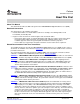
Preface SPRU978E – March 2008 Read This First About This Manual This document describes the DSP subsystem in the TMS320DM643x Digital Media Processor (DMP). Notational Conventions This document uses the following conventions. • Hexadecimal numbers are shown with the suffix h. For example, the following number is 40 hexadecimal (decimal 64): 40h. • Registers in this document are shown in figures and described in tables.
TMS320C6000, C6000 are trademarks of Texas Instruments.
Chapter 1 SPRU978E – March 2008 Introduction Topic 1.1 1.2 1.3 .................................................................................................. Page Introduction.............................................................................. 12 Block Diagram .......................................................................... 12 DSP Subsystem in TMS320DM643x DMP .....................................
www.ti.com Introduction 1.1 Introduction The TMS320DM643x Digital Media Processor (DMP) contains a powerful DSP to efficiently handle image, video, and audio processing tasks. The DM643x DMP consists of the following primary components and sub-systems: • DSP Subsystem (DSPSS), including the C64x+ Megamodule and associated memory.
www.ti.com DSP Subsystem in TMS320DM643x DMP 1.3 DSP Subsystem in TMS320DM643x DMP In the DM643x DMP, the DSP subsystem is responsible for performing digital signal processing for digital media applications. In addition, the DSP subsystem acts as the overall system controller, responsible for handling many system functions such as system-level initialization, configuration, user interface, user command execution, connectivity functions, and overall system control. 1.3.
Introduction SPRU978E – March 2008 Submit Documentation Feedback
Chapter 2 SPRU978E – March 2008 TMS320C64x+ Megamodule Topic 2.1 2.2 2.3 2.4 .................................................................................................. Introduction.............................................................................. TMS320C64x+ CPU.................................................................... Memory Controllers ................................................................... Internal Peripherals .................................................
www.ti.com Introduction 2.1 Introduction The C64x+ Megamodule (Figure 2-1) consists of the following components: • TMS320C64x+ CPU • Internal memory controllers: – Level-1 program memory controller (L1P controller) – Level-1 data memory controller (L1D controller) – Level-2 unified memory controller (L2 controller) – External memory controller (EMC) – Internal direct memory access (IDMA) controller • Internal peripherals – Interrupt controller (INTC) – Power-down controller (PDC) 2.
www.ti.com TMS320C64x+ CPU • • • • Protected mode operation: a two-level system of privileged program execution to support higher capability operating systems and system features, such as memory protection Exceptions support for error detection and program redirection to provide robust code execution Hardware support for modulo loop operation to reduce code size Industry's first assembly optimizer for rapid development and improved parallelization Figure 2-1.
www.ti.com Memory Controllers 2.3 Memory Controllers The C64x+ Megamodule implements a two-level internal cache-based memory architecture with external memory support. Level 1 memory is split into separate program memory (L1P memory) and data memory (L1D memory). Figure 2-2 shows a diagram of the memory architecture. L1P and L1D are configurable as part L1 RAM (normal addressable on-chip memory) and part L1 cache. L1 memory is accessible to the CPU without stalls.
www.ti.com Memory Controllers Figure 2-2.
www.ti.com Memory Controllers 2.3.2 L1D Controller The L1D controller is the hardware interface between level 1 data memory (L1D memory) and the other components in the C64x+ Megamodule (for example, C64x+ CPU, L2 controller, and EMC). The L1D controller responds to data requests from the C64x+ CPU and manages transfer operations between L1D memory and the L2 controller and between L1D memory and the EMC. Refer to the device-specific data manual for the amount of L1D memory on the device.
www.ti.com Memory Controllers 2.3.4 External Memory Controller (EMC) The external memory controller (EMC) is the hardware interface between the external memory map (external memory and external registers) and the other controllers in the C64x+ Megamodule (for example, L1P controller, L1D controller, and L2 controller). The EMC manages transfer operations between external memory and registers and the other memory controllers (L1P controller, L1D controller, and EMC).
www.ti.com Internal Peripherals 2.4 Internal Peripherals This C64x+ Megamodule includes the following internal peripherals: • Interrupt controller (INTC) • Power-down controller (PDC) This section briefly describes the INTC and PDC. For more information on these peripherals, see the TMS320C64x+ DSP Megamodule Reference Guide (SPRU871). 2.4.1 Interrupt Controller (INTC) The C64x+ Megamodule includes an interrupt controller (INTC) to manage CPU interrupts.
www.ti.com Internal Peripherals 2.4.
TMS320C64x+ Megamodule SPRU978E – March 2008 Submit Documentation Feedback
Chapter 3 SPRU978E – March 2008 System Memory Topic 3.1 3.2 .................................................................................................. Page Memory Map ............................................................................. 26 Memory Interfaces Overview ......................................................
www.ti.com Memory Map 3.1 Memory Map Refer to your device-specific data manual for memory-map information. 3.1.1 DSP Internal Memory (L1P, L1D, L2) This section describes the configuration of the DSP internal memory in the DM643x DMP that consists of L1P, L1D, and L2. In the DM643x DMP: • L1P memory: The L1P controller allows you to configure part or all of the L1P RAM as normal program RAM or as direct mapped cache. You can configure cache sizes of 0 KB, 4 KB, 8 KB, 16 KB, or 32 KB of the RAM.
www.ti.com Memory Interfaces Overview 3.2 Memory Interfaces Overview This section describes the different memory interfaces of DM643x DMP. The DM643x DMP supports several memory and external device interfaces, including the following: • DDR2 synchronous DRAM • Asynchronous EMIF/NOR/NAND Flash 3.2.1 DDR2 External Memory Interface The DDR2 external memory interface (EMIF) port is a dedicated interface to DDR2 SDRAM.
System Memory SPRU978E – March 2008 Submit Documentation Feedback
Chapter 4 SPRU978E – March 2008 Device Clocking Topic 4.1 4.2 .................................................................................................. Page Overview .................................................................................. 30 Clock Domains .........................................................................
www.ti.com Overview 4.1 Overview The DM643x DMP requires one primary reference clock. The primary reference clock can be either crystal input or driven by external oscillators. A 27 MHZ crystal at the MXI/CLKIN pin is recommended for the system PLLs, which generate the clocks for the DSP, peripherals, DMA, and imaging peripherals. The recommended 27 MHZ input enables you to use the video DACs to drive NTSC/PAL television signals at the proper frequencies.
www.ti.com Clock Domains Figure 4-1.
www.ti.com Clock Domains 4.2.2 Core Frequency Flexibility The core frequency domain clocks are supplied by the PLL controller 1 (PLLC1). These domain clocks are flexible, to a degree, within the limitations specified in the device-specific data manual. All of the following frequency ranges and multiplier/divider ratios in the data manual must be adhered to: • Input clock frequency range (MXI/CLKIN) • PLL1 multiplier (PLLM) range • PLL1 output (PLLOUT) frequency range based on the core voltage (1.05V or 1.
www.ti.com Clock Domains 4.2.3 DDR2/EMIF Clock The DDR2 interface has a dedicated clock driven from PLL2. This is a separate clock system from the PLL1 clocks provided to other components of the system. This dedicated clock allows the reduction of the core clock rates to save power while maintaining the required minimum clock rate (125 MHZ) for DDR2. PLL2 must be configured to output a 2× clock to the DDR2 PHY interface.
www.ti.com Clock Domains 4.2.4 I/O Domains The I/O domains refer to the frequencies of the peripherals that communicate through device pins. In many cases, there are frequency requirements for a peripheral pin interface that are set by an outside standard and must be met. It is not necessarily possible to obtain these frequencies from the on-chip clock generation circuitry, so the frequencies must be obtained from external sources and are asynchronous to the core frequency domain by definition.
www.ti.com Clock Domains 4.2.5 Video Processing Back End The video processing back end (VPBE) is a submodule of the video processing subsystem (VPSS). The VPBE must interface with a variety of LCDs, as well as the 4-channel DAC module. There are many different types of LCDs, which require many different specific frequencies. The range of frequencies that the pin interface needs to run is 6.25 MHZ to 75 MHZ. There are two asynchronous clock domains in the VPBE: the external clock domain (6.
www.ti.com Clock Domains Table 4-6. Possible Clocking Modes VPSS_CLKCTL.MUXSEL Bit 36 Clocking Mode Description 0 MXI mode Both the VENC and the DAC get their clock from PLLC1 SYSCLKBP, which defaults to the MXI 27 MHZ crystal input divide by 1. 1h PLL2 mode The PLL2 (divided-down) generates a 54 MHZ clock. Both the DAC and the VENC receive the 54 MHZ. The VENC can optionally divide it by 2 to create a 27 MHZ clock.
Chapter 5 SPRU978E – March 2008 PLL Controller Topic 5.1 5.2 5.3 5.4 .................................................................................................. PLL Module .............................................................................. PLL1 Control ............................................................................ PLL2 Control ............................................................................ PLL Controller Registers .............................................
www.ti.com PLL Module 5.1 PLL Module The DM643x DMP has two PLLs (PLL1 and PLL2) that provide clocks to different parts of the system. PLL1 provides clocks (though various dividers) to most of the components of the DM643x DMP. PLL2 is dedicated to the DDR2 port and components for the video processing subsystem (VPSS). The typical reference clock is the 27 MHZ crystal input, as mentioned in Chapter 4.
www.ti.com PLL1 Control Figure 5-1. PLL1 Structure in the TMS320DM643x DMP CLKMODE PLLEN CLKIN PLLOUT 1 PLL OSCIN PLLDIV1 (/1) SYSCLK1 (CLKDIV1 Domain) PLLDIV2 (/3) SYSCLK2 (CLKDIV3 Domain) PLLDIV3 (/6) SYSCLK3 (CLKDIV6 Domain) 1 0 0 PLLM AUXCLK (CLKIN Domain) BPDIV OSCDIV1 SYSCLKBP (VPSS-VPBR Clock Source) OBSCLK (CLKOUT0 Pin) 5.2.1 Device Clock Generation PLLC1 generates several clocks from the PLL1 output clock for use by the various processors and modules.
www.ti.com PLL1 Control 5.2.2.1 Initialization to PLL Mode from PLL Power Down If the PLL is powered down (PLLPWRDN bit in PLLCTL is set to 1), you must follow the procedure below to change PLL1 frequencies. The recommendation is to stop all peripheral operation before changing the PLL1 frequency, with the exception of the C64x+ DSP and DDR2. The C64x+ DSP must be operational to program the PLL controller. DDR2 operates off of the clock from PLLC2. 1.
www.ti.com PLL1 Control 5.2.2.2 Changing PLL Multiplier If the PLL is not powered down (PLLPWRDN bit in PLLCTL is cleared to 0) and the PLL stabilization time is previously met (step 7 in Section 5.2.2.1), follow this procedure to change PLL1 multiplier. The recommendation is to stop all peripheral operation before changing the PLL multiplier, with the exception of the C64x+ DSP and DDR2. The C64x+ DSP must be operational to program the PLL controller. DDR2 operates off of the clock from PLLC2. 1.
www.ti.com PLL1 Control 5.2.2.3 Changing SYSCLK Dividers This section discusses the software sequence to change the SYSCLK dividers. The SYSCLK divider change sequence is also referred to as GO operation, as it involves hitting the GO bit (GOSET bit in PLLCMD) to initiate the divider change. The recommendation is to stop all peripheral operation before changing the SYSCLK dividers, with the exception of the C64x+ DSP and DDR2. The C64x+ DSP must be operational to program the PLL controller.
www.ti.com PLL2 Control 5.3 PLL2 Control PLL2 provides the clock from which the DDR2 memory controller and optional VPBE clocks are derived. The DDR PLL controller 2 (PLLC2) controls PLL2, which accepts the clock from the oscillator and also generates the various frequency clocks needed. Figure 5-2 shows the customization of PLL2 in the DM643x DMP.
www.ti.com PLL2 Control 5.3.2 Steps for Changing PLL2 Frequency The PLLC2 is programmed similarly to the PLLC1. Refer to the appropriate subsection on how to program the PLL2 clocks: • If the PLL is powered down (PLLPWRDN bit in PLLCTL is set to 1), follow the full PLL initialization procedure in Section 5.3.2.2 to initialize the PLL. • If the PLL is not powered down (PLLPWRDN bit in PLLCTL is cleared to 0), follow the sequence in Section 5.3.2.3 to change the PLL multiplier.
www.ti.com PLL2 Control 5.3.2.2 Initialization to PLL Mode from PLL Power Down If the PLL is powered down (PLLPWRDN bit in PLLCTL is set to 1), you must follow the procedure below to change PLL2 frequencies. 1. Select the clock mode by programming the CLKMODE bit in PLLCTL. 2. Before changing the PLL frequency, switch to PLL bypass mode: a. Clear the PLLENSRC bit in PLLCTL to 0 to allow PLLCTL.PLLEN to take effect. b. Clear the PLLEN bit in PLLCTL to 0 (select PLL bypass mode). c.
www.ti.com PLL2 Control 5.3.2.3 Changing PLL Multiplier If the PLL is not powered down (PLLPWRDN bit in PLLCTL is cleared to 0) and the PLL stabilization time is previously met (step 7 in Section 5.3.2.2), follow this procedure to change PLL2 multiplier. 1. Before changing the PLL frequency, switch to PLL bypass mode: a. Clear the PLLENSRC bit in PLLCTL to 0 to allow PLLCTL.PLLEN to take effect. b. Clear the PLLEN bit in PLLCTL to 0 (select PLL bypass mode). c.
www.ti.com PLL2 Control 5.3.2.4 Changing SYSCLK Dividers This section discusses the software sequence to change the SYSCLK dividers. The SYSCLK divider change sequence is also referred to as GO operation, as it involves hitting the GO bit (GOSET bit in PLLCMD) to initiate the divider change. 1. Check for the GOSTAT bit in PLLSTAT to clear to 0 to indicate that no GO operation is currently in progress. 2. Program the RATIO field in PLLDIV1 and PLLDIV2 with the desired divide factors.
www.ti.com PLL Controller Registers 5.4 PLL Controller Registers Table 5-3 lists the base address and end address for the PLL controllers. Table 5-4 lists the memory-mapped registers for the PLL and reset controller. See the device-specific data manual for the memory address of these registers. Table 5-3. PLL and Reset Controller List PLL and Reset Controller Base Address End Address Size PLLC1 1C4 0800h 1C4 0BFFh 400h PLLC2 1C4 0C00h 1C4 0FFFh 400h Table 5-4.
www.ti.com PLL Controller Registers 5.4.1 Peripheral ID Register (PID) The peripheral ID register (PID) is shown in Figure 5-3 and described in Table 5-5. Figure 5-3. Peripheral ID Register (PID) 31 24 23 16 Reserved TYPE R-0 R-1h 15 8 7 0 CLASS REV R-8h R-Dh LEGEND: R = Read only; -n = value after reset Table 5-5.
www.ti.com PLL Controller Registers 5.4.3 PLL Control Register (PLLCTL) The PLL control register (PLLCTL) is shown in Figure 5-5 and described in Table 5-7. Figure 5-5. PLL Control Register (PLLCTL) 31 16 Reserved R-0 15 5 4 3 2 1 0 Reserved 9 CLKMODE 8 Reserved 7 6 PLLENSRC PLLDIS PLLRST Rsvd PLLPWRDN PLLEN R-0 R/W-0 R-1h R/W-1 R/W-1 R/W-0 R-0 R/W-1 R/W-0 LEGEND: R/W = Read/Write; R = Read only; -n = value after reset Table 5-7.
www.ti.com PLL Controller Registers 5.4.4 PLL Multiplier Control Register (PLLM) The PLL multiplier control register (PLLM) is shown in Figure 5-6 and described in Table 5-8. Figure 5-6. PLL Multiplier Control Register (PLLM) 31 16 Reserved R-0 15 5 4 0 Reserved PLLM R-0 R/W-10h or 13h (1) LEGEND: R/W = Read/Write; R = Read only; -n = value after reset (1) For PLLC1, PLLM defaults to 10h (PLL1 multiply by 17); for PLLC2, PLLM defaults to 13h (PLL2 multiply by 20). Table 5-8.
www.ti.com PLL Controller Registers 5.4.6 PLL Controller Divider 2 Register (PLLDIV2) The PLL controller divider 2 register (PLLDIV2) is shown in Figure 5-8 and described in Table 5-10. Divider 2 controls divider for SYSCLK2. Figure 5-8.
www.ti.com PLL Controller Registers 5.4.8 Oscillator Divider 1 Register (OSCDIV1) The oscillator divider 1 register (OSCDIV1) is shown in Figure 5-10 and described in Table 5-12. The oscillator divider 1 controls divider for OBSCLK, dividing down from the MXI/CLKIN clock. For PLLC1, the OBSCLK is connected to CLKOUT0 pin. OSCDIV1 only applies to PLLC1, and should not be used on PLLC2. Figure 5-10.
www.ti.com PLL Controller Registers 5.4.9 Bypass Divider Register (BPDIV) The bypass divider register (BPDIV) is shown in Figure 5-11 and described in Table 5-13. Bypass divider controls divider for SYSCLKBP, dividing down from the MXI/CLKIN clock. Figure 5-11.
www.ti.com PLL Controller Registers 5.4.10 PLL Controller Command Register (PLLCMD) The PLL controller command register (PLLCMD) is shown in Figure 5-12 and described in Table 5-14. PLLCMD contains the command bit for the GO operation. Writes of 1 initiate command. Writes of 0 clear the bit, but have no effect. Figure 5-12. PLL Controller Command Register (PLLCMD) 31 16 Reserved R-0 15 1 0 Reserved GOSET R-0 R/W-0 LEGEND: R/W = Read/Write; R = Read only; -n = value after reset Table 5-14.
www.ti.com PLL Controller Registers 5.4.12 PLL Controller Clock Align Control Register (ALNCTL) The PLL controller clock align control register (ALNCTL) is shown in Figure 5-14 and described in Table 5-16. ALNCTL indicates which SYSCLKs need to be aligned for proper device operation. You should not modify ALNCTL from its default settings. Figure 5-14.
www.ti.com PLL Controller Registers 5.4.13 PLLDIV Ratio Change Status Register (DCHANGE) The PLLDIV ratio change status register (DCHANGE) is shown in Figure 5-15 and described in Table 5-17. DCHANGE indicates if the SYSCLK divide ratio has been modified. Figure 5-15. PLLDIV Ratio Change Status Register (DCHANGE) 31 16 Reserved R-0 15 2 1 0 Reserved 3 SYS3 SYS2 SYS1 R-0 R-0 (1) R-0 R-0 LEGEND: R = Read only; -n = value after reset (1) For PLLC2, SYS3 is reserved and defaults to 0.
www.ti.com PLL Controller Registers 5.4.14 Clock Enable Control Register (CKEN) The clock enable control register (CKEN) is shown in Figure 5-16 and described in Table 5-18. CKEN provides clock enable control for miscellaneous output clocks. CKEN is only applicable to PLLC1, not PLLC2. Figure 5-16. Clock Enable Control Register (CKEN) 31 16 Reserved R-0 15 1 0 Reserved 2 OBSEN AUXEN R-0 R/W-1 R/W-1 LEGEND: R/W = Read/Write; R = Read only; -n = value after reset Table 5-18.
www.ti.com PLL Controller Registers 5.4.15 Clock Status Register (CKSTAT) The clock status register (CKSTAT) is shown in Figure 5-17 and described in Table 5-19. CKSTAT shows clock status for all clocks, except SYSCLKn. Figure 5-17.
www.ti.com PLL Controller Registers 5.4.16 SYSCLK Status Register (SYSTAT) The SYSCLK status register (SYSTAT) is shown in Figure 5-18 and described in Table 5-20. Indicates SYSCLK on/off status. Actual default is determined by actual clock on/off status, which depends on the D[n]EN bit in PLLDIV[n] default. Figure 5-18.
Chapter 6 SPRU978E – March 2008 Power and Sleep Controller Topic 6.1 6.2 6.3 6.4 6.5 6.6 6.7 .................................................................................................. Introduction.............................................................................. Power Domain and Module Topology .......................................... Power Domain and Module States ............................................... Executing State Transitions ..........................................
www.ti.com Introduction 6.1 Introduction The Power and Sleep Controller (PSC) is responsible for managing transitions of system power on/off, clock on/off, and reset. The DM643x DMP only utilizes the clock gating feature of the PSC for power savings. The PSC consists of a Global PSC (GPSC) and a set of Local PSCs (LPSCs). The GPSC contains memory mapped registers, PSC interrupt control, and a state machine for each peripheral/module.
www.ti.com Power Domain and Module Topology 6.2 Power Domain and Module Topology The DM643x DMP includes one power domain--the AlwaysOn power domain. The AlwaysOn power domain is always on when the chip is on. The AlwaysOn domain is powered by the VDD pins of the DM643x DMP (see the device-specific data manual). All of the DM643x DMP modules reside within the AlwaysOn power domain. Table 6-1 lists all the possible peripherals on the DM643x DMP, their LPSC assignments, and default module states.
www.ti.com Power Domain and Module States 6.3 Power Domain and Module States Note: The effects of DSP local reset and DSP module reset have not been fully validated; therefore, these resets are not supported and should not be used. Instead, the POR or RESET pins should be used to reset the entire DSP. Table 6-1 shows the state of each module after chip Power-on Reset (POR), Warm Reset (RESET), or Max Reset. These states are defined in the following sections. 6.3.
www.ti.com Executing State Transitions 6.3.3 Local Reset In addition to module reset (described in Section 6.3.2), the DSP CPU can be reset using a special local reset. When DSP local reset is asserted, the DSPs internal memories (L1P, L1D, and L2) are still accessible. The local reset only resets the DSP CPU core, not the rest of the DSP subsystem, as the DSP module reset would.
www.ti.com IcePick Emulation Support in the PSC 6.5 IcePick Emulation Support in the PSC The PSC supports IcePick commands that allow IcePick aware emulation tools to have some control over the state of power domains and modules. On the DM643x DMP, this IcePick support only applies to the C64x+ CPU (module number 39 in the AlwaysOn power domain 0). In particular, Table 6-3 shows IcePick emulation commands recognized by the PSC, and indicated ones that apply to the C64x+ CPU on the DM643x DMP. Table 6-3.
www.ti.com PSC Interrupts The DM643x DMP is a single-processor device. The C64x+ CPU must not program its own module state. The C64x+ CPU module state can only be programmed by an external host (for example, PCI, HPI). As a result, interrupt events listed in Table 6-4 can only occur in the scenario where an external host programs the C64x+ CPU module state but the emulator alters that desired state. 6.6.1.
www.ti.com PSC Registers 6.6.3 Interrupt Handling Handle the PSC interrupts as described in the following procedure: First, enable the interrupt. 1. Set the EMUIHBIE bit and the EMURSTIE bit in MDCTL39 to enable the interrupt events that you want. Note: The PSC interrupt PSCINT is sent to the DSP interrupt controller when at least one enabled event becomes active. 2. Enable the power and sleep controller interrupt (PSCINT) in the DSP interrupt controller.
www.ti.com PSC Registers 6.7.1 Peripheral Revision and Class Information Register (PID) The peripheral revision and class information (PID) register is shown in Figure 6-2 and described in Table 6-6. Figure 6-2. Peripheral Revision and Class Information Register (PID) 31 30 29 28 27 16 SCHEME Reserved FUNC R-1 R-0 R-482h 15 11 10 8 7 6 5 0 RTL MAJOR CUSTOM MINOR R-4h R-1 R-0 R-5h LEGEND: R = Read only; -n = value after reset Table 6-6.
www.ti.com PSC Registers 6.7.3 Module Error Pending Register 1 (MERRPR1) The module error pending register 1 (MERRPR1) is shown in Figure 6-4 and described in Table 6-8. Only the C64x+ CPU (module 39) can have an error condition, as it is the only module with IcePick support. See Section 6.5 for more information. Figure 6-4. Module Error Pending Register 1 (MERRPR1) 31 16 Reserved R-0 15 8 7 6 0 Reserved M[39] Reserved R-0 R-0 R-0 LEGEND: R = Read only; -n = value after reset Table 6-8.
www.ti.com PSC Registers 6.7.5 Power Domain Transition Command Register (PTCMD) The power domain transition command register (PTCMD) is shown in Figure 6-6 and described in Table 6-10. Figure 6-6. Power Domain Transition Command Register (PTCMD) 31 16 Reserved R-0 15 1 0 Reserved GO[0] R-0 W-0 LEGEND: R = Read only; W = Write only; -n = value after reset Table 6-10.
www.ti.com PSC Registers 6.7.7 Power Domain Status 0 Register (PDSTAT0) The power domain status n register (PDSTAT0) is shown in Figure 6-8 and described in Table 6-12. PDSTAT0 applies to the AlwaysOn power domain. Figure 6-8. Power Domain Status 0 Register (PDSTAT0) 31 16 Reserved R-0 15 9 8 Reserved 10 PORDONE POR 7 Reserved 5 4 STATE 0 R-0 R-1 R-1 R-0 R-1 LEGEND: R = Read only; -n = value after reset Table 6-12.
www.ti.com PSC Registers 6.7.8 Power Domain Control 0 Register (PDCTL0) The power domain control n register (PDCTL0) is shown in Figure 6-9 and described in Table 6-13. PDCTL0 applies to the AlwaysOn power domain. Figure 6-9. Power Domain Control 0 Register (PDCTL0) 31 16 Reserved R-0 15 1 0 Reserved NEXT R-0 R/W-1 LEGEND: R/W = Read/Write; R = Read only; -n = value after reset Table 6-13.
www.ti.com PSC Registers 6.7.9 Module Status n Register (MDSTATn) The module status n register (MDSTAT0-MDSTAT39) is shown in Figure 6-10 and described in Table 6-14. Figure 6-10. Module Status n Register (MDSTATn) 31 18 15 13 17 16 Reserved EMUIHB EMURST R-0 R-0 R-0 12 11 10 9 8 Reserved MCKOUT Reserved MRST LRSTDONE LRST Reserved 7 6 5 STATE 0 R-0 R-0 R-1 R-0 R-1 R-1 R-0 R-0 LEGEND: R = Read only; -n = value after reset Table 6-14.
www.ti.com PSC Registers 6.7.10 Module Control n Register (MDCTLn) The module control n register (MDCTL0-MDCTL39) is shown in Figure 6-11 and described in Table 6-15. Figure 6-11. Module Control n Register (MDCTLn) 31 16 Reserved R-0 15 10 9 8 Reserved 11 EMUIHBIE EMURSTIE LRST 7 Reserved 3 2 NEXT 0 R-0 R/W-0 R/W-0 R/W-1 R-0 R/W-0 LEGEND: R/W = Read/Write; R = Read only; -n = value after reset Table 6-15.
Power and Sleep Controller SPRU978E – March 2008 Submit Documentation Feedback
Chapter 7 SPRU978E – March 2008 Power Management Topic 7.1 7.2 7.3 7.4 7.5 7.6 .................................................................................................. Overview .................................................................................. PSC and PLLC Overview ............................................................ Clock Management .................................................................... DSP Sleep Mode Management ...........................................
www.ti.com Overview 7.1 Overview In many applications, there may be specific requirements to minimize power consumption for both power supply (or battery) and thermal considerations. There are two components to power consumption: active power and leakage power. Active power is the power consumed to perform work and scales roughly with clock frequency and the amount of computations being performed.
www.ti.com Clock Management 7.3 Clock Management 7.3.1 Module Clock ON/OFF The module clock on/off feature allows software to disable clocks to module individually, in order to reduce the module's active power consumption to 0. The DM643x DMP is designed in full static CMOS; thus, when a module clock stops, the module's state is preserved. When the clock is restarted, the module resumes operating from the stopping point.
www.ti.com DSP Sleep Mode Management 7.4 DSP Sleep Mode Management The C64x+ DSP supports sleep mode management to reduce power: • DSP clock can be completely shut off • C64x+ Megamodule can be put in sleep mode – C64x+ CPU can be put in sleep mode On the DM643x DMP, sleep mode for the DSP internal memories (L1P, L1D, L2) is not supported. 7.4.
www.ti.com 3.3 V I/O Power Down 7.4.2.2 DSP Module Clock Off In the clock Disable state, the DSP’s module clock is disabled, while DSP reset remains de-asserted. This state is typically used to disable the DSP clock to save power. As mentioned in Section 7.4.2, the DSP cannot put itself in Disable state. An external host is responsible for performing this task. For example, it can be an external host interfacing through the HPI or PCI peripheral. • Host: Notify the DSP to prepare for power-down.
Power Management SPRU978E – March 2008 Submit Documentation Feedback
Chapter 8 SPRU978E – March 2008 Interrupt Controller The C64x+ Megamodule includes an interrupt controller (INTC) to manage CPU interrupts. The interrupt controller interfaces the system events to the CPU's interrupt and exception inputs. The interrupt controller supports up to 128 system events, and it maps these system events to the 12 CPU interrupts. See the device-specific data manual for the list of system events.
Interrupt Controller SPRU978E – March 2008 Submit Documentation Feedback
Chapter 9 SPRU978E – March 2008 System Module Topic 9.1 9.2 9.3 9.4 9.5 9.6 9.7 .................................................................................................. Overview .................................................................................. Device Identification .................................................................. Device Configuration ................................................................. 3.3 V I/O Power-Down Control ................................
www.ti.com Overview 9.1 Overview The TMS320DM643x DMP System Module is a system-level module containing status and top-level control logic required by the device. The System Module consists of a set of status and control registers, accessible by the DSP, supporting all of the following system features and operations: • Device Identification • Device Configuration – Pin multiplexing control – Device boot configuration status • Power Management – VDD 3.
www.ti.com 3.3 V I/O Power-Down Control 9.4 3.3 V I/O Power-Down Control The VDD3P3V_PWDN register controls power to the 3.3 V I/O cells. Some 3.3 V I/Os default to power down for power saving. See device-specific data manual for the description of the VDD3P3V_PWDN register. 9.5 Peripheral Status and Control Several of the DM643x DMP peripheral modules require additional system-level control logic. Those registers are discussed in this section. 9.5.
www.ti.com Bandwidth Management 9.6 Bandwidth Management 9.6.1 Bus Master DMA Priority Control In order to determine allowed connections between masters and slaves, each master request source must have a unique master ID (mstid) associated with it. The master ID for each DM643x DMP master is shown in Table 9-1. Table 9-1.
www.ti.com Boot Control Each switched central resource (SCR) performs prioritization based on the priority level of the master that sends the command. Each bus master's priority is programmed in the chip-level Bus Master Priority Control Registers (MSTPRI0 or MSTPRI1). The default priority level for each bus master is shown in Table 9-2. Application software is expected to modify these values to obtain the desired system performance. Table 9-2.
System Module SPRU978E – March 2008 Submit Documentation Feedback
Chapter 10 SPRU978E – March 2008 Reset Topic .................................................................................................. 10.1 10.2 10.3 10.4 Overview .................................................................................. Reset Pins ................................................................................ Device Configurations at Reset................................................... DSP Reset ...................................................................
www.ti.com Overview 10.1 Overview There are different types of reset in the TMS320DM643x DMP. The types of reset differ by how they are initiated and/or by their effect on the chip. Each type is briefly described in Table 10-1. Refer to the device-specific data manual for more details on each of the reset types. Table 10-1. Reset Types Type Initiator Effect POR (Power-On-Reset) POR pin low Total reset of the chip (cold reset). Resets all modules including memory, emulation logic.
www.ti.com DSP Reset 10.4 DSP Reset Note: The effects of DSP local reset and DSP module reset have not been fully validated; therefore, these resets are not supported and should not be used. Instead, the POR or RESET pins should be used to reset the entire DSP. With access to the power and sleep controller (PSC) registers, the external host (for example, PCI or HPI) can assert and de-assert DSP local reset and DSP module reset.
www.ti.com DSP Reset • Host: Assert the DSP local reset (Optional) – Clear the LRST bit in MDCTL39 to 0. This step is optional. This step asserts the DSP local reset, and is included here so that the DSP does not start running immediately upon it is subsequently enable by the host. Typically, the host only de-asserts local reset to the DSP after it makes sure that code is properly loaded. 10.4.2.
Chapter 11 SPRU978E – March 2008 Boot Modes The TMS320DM643x DMP can boot from either asynchronous EMIF/NOR Flash directly or from internal boot ROM, as determined by the setting of the device boot and configuration pins. The input states of the boot and configuration pins are sampled and latched into the BOOTCFG register when device reset is deasserted. Refer to the device-specific data manual for the list of boot and configuration pins and a list of boot modes supported on the DM643x DMP.
Boot Modes SPRU978E – March 2008 Submit Documentation Feedback
Appendix A SPRU978E – March 2008 Revision History Table A-1 lists the changes made since the previous version of this document. Table A-1. Document Revision History Reference Additions/Modifications/Deletions Figure 6-1 Added Note. Section 6.3 Added Note. Section 10.4 Added Note.
IMPORTANT NOTICE Texas Instruments Incorporated and its subsidiaries (TI) reserve the right to make corrections, modifications, enhancements, improvements, and other changes to its products and services at any time and to discontinue any product or service without notice. Customers should obtain the latest relevant information before placing orders and should verify that such information is current and complete.