
User's Manual


Application Report
SLLA032
TNETE2201 EVM Kit Setup and Usage 3
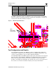
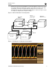
Board Layout and Configuration
The TNETE2201 EVM kit is designed to give the developer many options for operation.
Many of these options are selectable by DIP switch and others may require board
component removal or additions. The following sections provide guidelines to configure
the EVM kit for different modes of operation.
The EVM kit is normally delivered in a default configuration that requires external clock
and data inputs. The high-speed serial input and output are routed through the 50-ohm
transmission line path. The GBIC interface is not connected and would require some
resistor modifications to be functional. The default setup is useful for testing the board
and interface IC. The designer might consider testing the bit error rate, jitter, and eye-
diagram characteristics of the system. The TNETE2201 EVM is shipped with certain
components installed for default operation. Table 1 lists the default configuration.
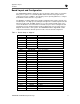
Table 1. Default Setup as Shipped
Designator Function Condition (TNETE2201)
P5 CLK SEL Jumper installed between Pins 2 and 3
R1 TX Termination 200 ohm installed
R2 TX Termination 200 ohm installed
R5 Bias Net 365 ohm installed
R6 Bias Net 562 ohm installed
R8 WIZ OPTION Not installed
R9 WIZ OPTION Not installed
R16 CAP OPTION Zero ohm installed
R17 Bias Net Not installed
R21 WIZ OPTION Not installed
R22 WIZ OPTION Not installed
C13 Vcc Decouple 0.01 µF installed
C23 GBIC OPTION Not installed
C24 SMA OPTION 0.01 µF installed
C25 GBIC OPTION Not installed
C26 SMA OPTION 0.01 µF installed
C27 SMA OPTION 0.01 µF installed
C28 GBIC OPTION Not installed
C29 GBIC OPTION Not installed
C30 SMA OPTION 0.01 µF installed
C31 RX Termination 0.01 µF installed
C32 TX PLL Cap 0.0022 µF installed
C33 REF CLK Bias Net Zero 0hm installed
C34 TX PLL Cap 0.0022 µF installed
L1 Filter/Bias Ferrite installed
X1 OSC Not installed (not provided)
DIP1-1 PRBSEN X (OFF)
DIP1-2 TXRRAMP X (OFF)
DIP1-3 TXDIR X (OFF)