
User's Manual


Application Report
SLLA032
TNETE2201 EVM Kit Setup and Usage 5
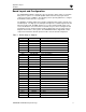
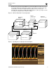
Both the pulse generator and the BERT are synchronized with an external clock source.
The operator adjusts the variable phase delay to ensure that the clock meets the setup
and hold time of the data. The parallel data along with the clock is routed to the
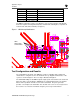
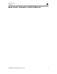
transmitter where the data is serialized and captured by the oscilloscope. Figure 3 shows
an example eye diagram taken using this technique.
Figure 2. Bit Error-Rate Ratio Test Configuration
Wizard
(With parallel
ports looped)
HP71603B
BERT
HP54750A
Digital O’Scope
RX-
RX+
TX+
TX-
Data Out
Data Out
Data In
36”
36”
Channel 1
36”
HP8133A
Pulse Generator
Clk Out
REFCLK
(Variable Delay)
36”
Sync
Sync
External Clock
For Sync
Figure 3. Eye Diagrams of High-Speed Serial Outputs