
User's Manual

6.3 TCP2 Input Configuration Register 1 (TCPIC1)
6.4 TCP2 Input Configuration Register 2 (TCPIC2)
www.ti.com
Registers
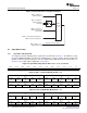
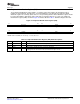
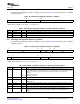
The TCP2 input configuration register 1 (TCPIC1) is shown in Figure 34 and described in Table 7 . TCPIC1
configures the TCP.
Figure 34. TCP2 Input Configuration Register 1 (TCPIC1)
31 23 22 16 15 0
Reserved R Reserved
R/W-0 R/W-0 R/W-0
LEGEND: R/W = Read/Write; R = Read only; - n = value after reset
Table 7. TCP2 Input Configuration Register 1 (TCPIC1) Field Desccriptions
Bit Field Value Description
31-23 Reserved 0 Reserved. The reserved bit location is always read as 0. A value written to this field has no effect.
22-16 R 39-127 Reliability length + 1: 7 bits (min = 39, max = 127).
14-0 Reserved 0 Reserved. The reserved bit location is always read as 0. A value written to this field has no effect.
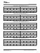
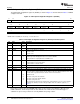
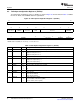
The TCP2 input configuration register 2 (TCPIC2) is shown in Figure 35 and described in Table 8 . TCPIC2
configures the TCP.
Figure 35. TCP2 Input Configuration Register 2 (TCPIC2)
31 24 23 21 20 16
SNR Reserved MAXIT
R/W-0 R/W-0 R/W-0
15 14 8 7 6 5 0
Rsvd NSB Reserved P
R/W-0 R/W-0 R/W-0 R/W-0
LEGEND: R/W = Read/Write; R = Read only; - n = value after reset
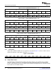
Table 8. TCP2 Input Configuration Register 2 (TCPIC2) Field Descriptions
Bit Field Value Description
31-24 SNR 0-100 SNR threshold. SNR is used for stopping test (8 bits). The turbo decoding will stop as soon as the
decoded signal SNR ratio > SNR threshold ratio. The maximum value is 100, giving a value of zero
disables this test and the decoder will execute the number of iterations given in the above
parameter.
0 Disables ratio threshold
1 to 100 Enables threshold ratio
23-21 Reserved 0 Reserved. The reserved bit location is always read as 0. A value written to this field has no effect.
20-16 MAXIT 0-31 Maximum number of iterations: 5 bits (0-31). 0 means 32 iterations.
0 Sets MAXIT to 32.
15 Reserved 0 Reserved. The reserved bit location is always read as 0. A value written to this field has no effect.
14-8 NSB 0-81 Number of sub-blocks. For shared processing mode only.
7-6 Reserved 0 Reserved. The reserved bit location is always read as 0. A value written to this field has no effect.
5-0 P 4-48 Prolog length (from 4 to 48). Sliding window prolog length, maximum is 48, minimum is 4. In
shared-processing mode, the prolog length must be a multiple of 8, due to EDMA3 transfers
alignment.
SPRUGK1 – March 2009 TMS320C6457 Turbo-Decoder Coprocessor 2 29
Submit Documentation Feedback