
User's Manual


Functional Description
14
SLES140A—March 2007TVP5147M1PFP
2.2.3 Luminance Processing
The digitized composite video signal passes through either a luminance comb filter or a chroma trap filter,
either of which removes chrominance information from the composite signal to generate a luminance signal.
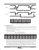
The luminance signal is then fed into the input of a peaking circuit. Figure 2−8 illustrates the basic functions
of the luminance data path. In the case of S-video, the luminance signal bypasses the comb filter or chroma
trap filter and is fed directly to the circuit. A peaking filter (edge enhancer) amplifies high-frequency
components of the luminance signal. Figure 2−9 shows the characteristics of the peaking filter at four different
gain settings that are user-programmable via the I
2
C interface.
Bandpass
Filter
×
Gain
Peaking
Filter
IN
+
OUT
Delay
Peak
Detector
Figure 2−8. Luminance Edge-Enhancer Peaking Block Diagram
f − Frequency − MHz
−1
0
1
2
3
4
5
6
7
01234567
Gain = 0
Gain = 2
Gain = 1
Gain = 0.5
Peak at
f = 2.64 MHz
Amplitude − dB
Figure 2−9. Peaking Filter Response,
NTSC/PAL ITU-R BT.601 Sampling
2.2.4 Color Transient Improvement
Color transient improvement (CTI) enhances horizontal color transients. The color difference signal transition
points are maintained, but the edges are enhanced for signals which have bandwidth-limited color
components.