User’s Guide SLUU068C
User’s Guide February 2005 -2 Power Management Products SLUU068C
IMPORTANT NOTICE Texas Instruments Incorporated and its subsidiaries (TI) reserve the right to make corrections, modifications, enhancements, improvements, and other changes to its products and services at any time and to discontinue any product or service without notice. Customers should obtain the latest relevant information before placing orders and should verify that such information is current and complete.
EVM IMPORTANT NOTICE Texas Instruments (TI) provides the enclosed product(s) under the following conditions: This evaluation kit being sold by TI is intended for use for ENGINEERING DEVELOPMENT OR EVALUATION PURPOSES ONLY and is not considered by TI to be fit for commercial use.
EVM WARNINGS AND RESTRICTIONS It is important to operate this EVM within the input voltage range of 85 V to 265 V and the output voltage of 12 V +/− 5%. Exceeding the specified input range may cause unexpected operation and/or irreversible damage to the EVM. If there are questions concerning the input range, please contact a TI field representative prior to connecting the input power.
Contents Contents 1 General Information . . . . . . . . . . . . . . . . . . . . . . . . . . . . . . . . . . . . . . . . . . . . . . . . . . . . . . . . . . . . . 1.1 Features . . . . . . . . . . . . . . . . . . . . . . . . . . . . . . . . . . . . . . . . . . . . . . . . . . . . . . . . . . . . . . . . . . 1.2 Description . . . . . . . . . . . . . . . . . . . . . . . . . . . . . . . . . . . . . . . . . . . . . . . . . . . . . . . . . . . . . . . . 1.3 Operating Guidelines . . . . . . . . . . . . . . . . .
Chapter 1 General Information This chapter details the Texas Instruments (TI) DM38500 PFC/PWM Combination Controller 100W Power Factor Correction Preregulator Evaluation Module (EVM) SLUU068. It includes a list of EVM features, a brief description of the module illustrated with a pictorial, schematic diagrams, and EVM specifications. Topic Page 1.1 Features . . . . . . . . . . . . . . . . . . . . . . . . . . . . . . . . . . . . . . . . . . . . . . . . . . . . . 1−2 1.2 Description . . . . . . . . . .
Features 1.
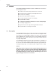
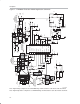
Description 1.3 Operating Guidelines The operating guidelines for the evaluation board are provided with reference to the schematic in Figure 1−1 and the component layout in Figure 2−1. 1.3.1 Step 1. Load Connections A resistive or electronic load can be applied to the output terminals labeled OUT− and OUT+. Note: For safety reasons the load should be connected before power is supplied to the demonstration board. 1.3.2 Step 2.
1-4 C26 D15 R3 L1 VCCBIAS CIRCUIT HIGH VOLTAGE − SEE EVM WARNINGS AND RESTRICTIONS AC−N AC−L VAC 85−265V RMS Q5 D7 R39 D11 D5 R24 R18 VCC BIAS CIRCUIT R29 C20 C12 D12 R10 C22 PKLIMIT R14 VREF R19 R5 GT1 L1 D1 C6 C19 R17 R15 VCC C24 PGND Q3 D3 R21 R20 SGND R30 GT2 T2 C27 VREF 20 VREF GND 6 RT 2 ISENSE2 8 VERR 7 SS2 13 PWRGND 11 14 PKLIMIT 19 VFF 18 IAC 15 CAOUT 17 MOUT CT 5 16 ISENSE GT2 10 GT1 12 VCC 9 VSENSE OVP/ENBL UCC38500 U4 D4 D2 R
DM38500 EVM Performance 1.4 DM38500 EVM Performance Figure 1−2 through 1−4 shows the typical evaluation module performance. Figure 1−2. DM38500 EVM Efficiency UCC38500 EFFICIENCY vs OUTPUT POWER 90 VIN = 265 V 85 Efficiency −% 80 VIN = 175 V 75 70 VIN = 85 V 65 60 55 50 10 20 30 40 50 60 70 80 90 100 POUT − W Figure 1−3. DM38500 Power Factor UCC38500 PF vs OUTPUT POWER Power Factor 1.00 VIN = 85 V 0.95 VIN = 265 V VIN = 175 V 0.90 0.
DM38500 EVM Performance Figure 1−4.
Chapter 2 Reference This chapter includes a parts list and PCB layout illustrations for the DM38500 EVM. Topic Page 2.1 DM38500 EVM Part Descriptions . . . . . . . . . . . . . . . . . . . . . . . . . . . 2−2 2.2 DM38500 Board Layouts . . . . . . . . . . . . . . . . . . . . . . . . . . . . . . . . . .
DM38500 EVM Part Descriptions 2.1 DM38500 EVM Part Descriptions Table 2−1.
DM38500 EVM Part Descriptions Description Resistors Transformers ICs Miscellaneous PCB Reference Qty Value/Type Number R1, R12 R10, R36 R25, R29, R27 R13 R14 R15, R19 R16 R17 R18, R24 R2, R11 R20 R21 R22, R33 R23 R26 R28 R30 R31 R32 R34 R35 R39 R4 R5 R6, R7 R3 T1 T2 2 2 Short 200 Ω, ¼ W 3 10 kΩ, ¼ W 1 1 2 1 1 2 2 1 1 2 1 1 1 1 1 1 1 1 1 1 1 2 1 1 1 U4 1 U3 1 X1 3 X2 1 X3 4 X4 4 X5 3 X6 PCB 1 1 2 kΩ, ¼ W 1.5 kΩ, ¼ W 3.92 kΩ, ¼ W 750 Ω, ¼ W 7.5 kΩ, ¼ W 392 kΩ, ¼ W 1 kΩ, ¼ W 22.
DM38500 Board Layouts 2.2 DM38500 Board Layouts Board layout examples of the DM38500 EVM PCB are shown in the following illustrations. They are not to scale and appear here only as a reference. Figure 2−1.