Thales Canada, Transportation Solutions 105 Moatfield Drive, Suite 100, Toronto, Ontario Canada Tel. +1 416 742 3900 Fax. + 1 416 742 1136 www.thalesgroup.com COMTRAC RADIO USER MANUAL Business Entity Identifier Business Identifier DTC Revision 9950-15900 3CU 04036 0026 PCZZA 108 0A CONFIDENTIAL © Thales Canada, Transportation Solutions. All rights reserved.
COMTRAC RADIO USER MAUAL REVISION HISTORY LOG OF CHANGES Revision Date Author Modification 0A 5-Dec-2018 D. Cammidge Initial Draft Business Entity Identifier Business Identifier DTC Revision 9950-15900 3CU 04036 0026 PCZZA 108 0A CONFIDENTIAL © Thales Canada, Transportation Solutions. All rights reserved. Passing on or copying of this document, use or communication of its content in whole or in part is not permitted without prior written authorization.
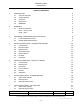
COMTRAC RADIO USER MAUAL TABLE OF CONTENTS 1. INTRODUCTION 1.1 Scope and Purpose 1.2 Target Audience 1.3 Acronyms 1.4 References 1.5 WARNING 5 5 5 5 6 6 2. OVERVIEW 2.1 Modes of Operation 2.1.1 Access Point 2.1.2 Client 7 8 8 8 3. SOFTWARE / CONFIGURATION INSTALLATION 3.1 Local Download Procedure 3.2 Remote Download Procedure 9 9 9 4. PHYSICAL INTERFACES – STANDALONE VARIANT 4.1 Console Ports 4.2 Discrete IO Port 4.3 Ethernet Ports 4.4 Fiber (SFP) Ports 4.5 Power Interface 4.6 RF Ports 4.
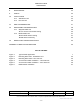
COMTRAC RADIO USER MAUAL 8. MAINTENANCE 22 9. SAFETY 23 10. INSTALLATION 10.1 Standalone Unit 10.2 Die-cast Unit 24 24 26 11. EMC CONSIDERATIONS 27 12. DEPLOYMENT CONSIDERATIONS 12.1 Wayside Radio Unit 12.1.1 Access Point Power Setting 12.2 Mobile Radio Unit 12.2.1 Mobile Power Setting 12.2.2 Antenna Diversity 28 29 30 31 31 32 13.
COMTRAC RADIO USER MAUAL 1. INTRODUCTION 1.1 Scope and Purpose This document is intended to provide an overview of the ComTrac Radio as well as basic information regarding installation. It is intended to be submitted as an artifact for regulatory compliance. 1.2 Target Audience The ComTrac Radio is an industrial grade device and not a consumer product. This manual is designed to be used by qualified technical support personnel with experience in the rail signalling environment. 1.
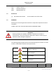
COMTRAC RADIO USER MAUAL 1.4 QoS Quality of Service USB Universal Serial Bus WRU Wayside Radio Unit References [1] 1.5 3CU 04036 0027 PCZZA ComTrac Radio Technician Guide WARNING Warnings are used throughout this document to emphasize important and critical information. COMPLY WITH ALL EXISTING ELECTRICAL WARNING SIGNS.
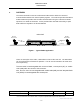
COMTRAC RADIO USER MAUAL OVERVIEW 2. The ComTrac Radio is used as a telecommunication device within the context of Communication Based Train Control (CBTC) System. The radio incorporates the 802.11 FHSS standard to provide radio-to-radio communication using the unlicensed 2.4GHz spectrum in a mobile environment. It also provides fiber and LAN connectivity to pass data traffic from wayside to on-board networks.
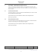
COMTRAC RADIO USER MAUAL 2.1 Modes of Operation 2.1.1 Access Point An access point (AP) is a mode of operation that allows connectivity, through bridging, from a wired local area network (LAN) to one or more clients. To setup the radio in AP mode requires the AP configuration file to be selected. Refer to the Configuration section in [1] for further details. 2.1.
COMTRAC RADIO USER MAUAL SOFTWARE / CONFIGURATION INSTALLATION 3. There are two methods to download software and configuration to the radio, a local method where physical connectivity to the radio is available, and a remote method, such as on a network. 3.1 Local Download Procedure This method requires a console connection to the administration port, as well as a USB drive formatted with FAT32 file system. This procedure may be used to update the software and/or configuration files.
COMTRAC RADIO USER MAUAL 4. PHYSICAL INTERFACES – STANDALONE VARIANT 4.1 Console Ports A console port is provided for each side. Side-A is interfaced through ADMIN-A, and the side-B is interfaced through ADMIN-B. The console interface uses a standard female DB9. The pin-outs are listed below. When using a USB to serial adaptor, it is recommended to keep the serial cable portion as short as possible. DB-9 Female RS-232 Signal Connector Pin Out 4.
COMTRAC RADIO USER MAUAL 4.3 Ethernet Ports These ports are shielded, RJ-45 ports that supports 10BaseT / 100BaseT / 1000BaseT Ethernet network connectivity. Short-circuit protection and 1500Vrms isolation is supported. There are four ports per side; A-side has connectivity to the ports labelled 1-A thru 4-A. B-side has connectivity to the ports labelled 1-B thru 4-B. 4.4 Fiber (SFP) Ports The radio contains two SFP slots. Ensure the transceiver modules are securely inserted and latched.
COMTRAC RADIO USER MAUAL 4.5 Power Interface The power port is label as ‘12 VDC’ and requires between 9-14Vdc to operate, with a minimum input current rating of 3A @12V. There is reverse polarity protection. The ‘pin’ on the radio is the positive connection, and the ‘socket’ negative. DSUB Female Connector Pin Out 12VDC 1 (pin) 2 (socket) +Vdc -Vdc The absolute maximum input voltage is 15V. The -Vdc is electrically connected to chassis.
COMTRAC RADIO USER MAUAL 4.6 RF Ports There are four RF N-type female, 50 ohm connectors, labelled below. For CBTC implementation, the following default antenna ports are identified below. RF Port STA AP ANT 1 ANT 2 ANT 3 ANT 4 Not used Not used Diversity (modem-0) Diversity (modem-1) Not used Not used Main Antenna Not used To avoid radio receiver saturation, the maximum input signal level to the radio should not exceed -10dBm. The absolute maximum continuous input power is +10dBm. 4.
COMTRAC RADIO USER MAUAL 5. PHYSICAL INTERFACES – DIE-CAST VARIANT 5.1 Console Ports The console ports are located underneath the removable face plate. A console port is provided for each side. Side-A is interfaced through ADMIN-A, and the side-B is interfaced through ADMIN-B. The console interface uses a standard female DB9. The pin-outs are listed below. When using a USB to serial adaptor, it is recommended to keep the serial cable portion as short as possible.
COMTRAC RADIO USER MAUAL 5.2 Ethernet Port This port is labeled on the top of the unit as ‘ETHERNET’. The interface is an M12 D-coded female connector that supports 10BaseT / 100BaseT Ethernet network connectivity. Short-circuit protection and 1500Vrms isolation is supported. It also supports a mating connector with a push-pull or threaded locking mechanism. In reference to the Standalone radio, this interface is internally connected to port 3-A, using a straight-through cable.
COMTRAC RADIO USER MAUAL 5.3 Fiber Ports There is one connector which contains two fiber interfaces, and is labelled ‘FIBER’ on the top of the unit. The connector is a Harting Han® 3 A with a locking feature, and uses an insert. In reference to the Standalone radio, this interface is internally connected to the SFP ports, using a fiber cable. Type of fiber is dependent on the variant of die-cast unit. The following shows the pin-out as well as the signal definition. I/O Label Fiber Port Pin # (ref.
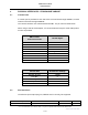
COMTRAC RADIO USER MAUAL 5.4 Power Interface The power port is label as ‘AC POWER INPUT’ on the top of the unit. The connector is a Harting series Han® 4 A, with a locking feature, and uses a 4 position (male) insert. The following indicates the pin-out as well as the signal definition. Power Connector Pin # 120-240Vac 1 2 3 4 Line (no connect) (no connect) Neutral GND GND The following table identifies a 1.5 meter power cable assembly using flexible conduit to be used between the radio and the PFSE.
COMTRAC RADIO USER MAUAL 5.5 RF Port There is one RF port located at the side of the unit, and is labeled as ANT-1 on the top of the unit. There is a series internal bandpass filter, which provides rejection for frequencies outside of the 2.4 GHz band. Refer to the Specification section for the RF characteristics. The RF port is an N-type female connector. 5.6 USB Ports The Universal Serial Bus (USB) ports are located underneath the removable face plate.
COMTRAC RADIO USER MAUAL 6. STATUS INDICATORS – STANDALONE UNIT 6.1 Status Fault Indicator The Status Fault LED indicator is used to indicate the operational status of the radio as indicated in the following table. It is located on the front and center of the unit, and is labelled as STATUS. STATUS LED LED is Green LED is Orange LED is Red 6.
COMTRAC RADIO USER MAUAL 6.3 Wireless Network Links The wireless network link uses a series of LEDs to indicate status. Only the yellow bank of LEDs is currently utilized, which is located underneath ANT 4. The green bank of LEDs is not functional. The following provides a description of their usage.
COMTRAC RADIO USER MAUAL 7. STATUS INDICATORS – DIE-CAST UNIT 7.1 Status Fault Indicator The Status Fault LED indicator is used to indicate the operational status of the radio as indicated in the following table. It is located on the front and center of the unit, and is labelled as STATUS. STATUS LED LED is Green LED is Orange LED is Red 7.
COMTRAC RADIO USER MAUAL 8. MAINTENANCE Mounting the radio should include consideration for the maintenance strategy in terms of ease of complexity and time of radio replacement. There are no serviceable parts within the radio. This applies to both the Standalone and Die-cast units. The Die-cast unit has an input fuse which is externally accessible and next to the input power connector. Refer to Power Interface section for details.
COMTRAC RADIO USER MAUAL 9. SAFETY Warning! LED or Laser components according to IEC 60825-1 (2001): CLASS 1 LASER PRODUCT. LIGHT EMITTING DIODE – CLASS 1 LED PRODUCT. WARNING – FIBER OPTIC INTERFACES LED LIGHT DO NOT STARE INTO THE BEAM OR VIEW DIRECTLY WITH OPTICAL INSTRUMENTS (e.g. lens, microscope). For Die-cast unit only: WARNING Proper precaution MUST be exercised when touching and working on the equipment, as AC voltage may be present when working on the Die-cast unit.
COMTRAC RADIO USER MAUAL 10. INSTALLATION The radio is not a consumer product, and therefore installation must be conducted by qualified personal, based on drawing approval by TCTS. 10.1 Standalone Unit The standalone variant of the radio has two mounting methods; using the mounting feet, or securing directly to the bottom. The mounting feet can accept a No. 10 (M5) screw. Securing to the bottom side uses No. 10-32 screws. Maximum depth is 11/32” (8.5mm). Refer to Figure 3 for mounting details.
COMTRAC RADIO USER MAUAL Figure 2 Mounting Dimensions Business Entity Identifier Business Identifier DTC Revision 9950-15900 3CU 04036 0026 PCZZA 108 0A CONFIDENTIAL © Thales Canada, Transportation Solutions. All rights reserved. Passing on or copying of this document, use or communication of its content in whole or in part is not permitted without prior written authorization.
COMTRAC RADIO USER MAUAL 10.2 Die-cast Unit The die-cast variant of the radio is designed for an outdoor environment, and has IP66 / NEMA 4X ratings. It also has a solar shield option. Contact TCTS for further details. The mounting holes accommodate No. 12 (M6) size screw. Figure 3 Mounting Dimensions – Die-cast Unit Business Entity Identifier Business Identifier DTC Revision 9950-15900 3CU 04036 0026 PCZZA 108 0A CONFIDENTIAL © Thales Canada, Transportation Solutions. All rights reserved.
COMTRAC RADIO USER MAUAL 11. EMC CONSIDERATIONS To ensure the radio is compliant with EMC emission standards, the radio must be connected to ground. It is recommended to use a braided cable kept as short as practical for this purpose. Maximum length between bonding points should be less than 1 meter. For the Standalone variant, this connection is located on the side of the unit, using the screw location with the open area around / underneath the screw head. It is identified by a ground symbol.
COMTRAC RADIO USER MAUAL 12. DEPLOYMENT CONSIDERATIONS In the context of CBTC deployment, careful considerations for bandwidth usage must be taken into account for traffic passing over the wireless interface. Quality of Service (QoS) is a mechanism to help prioritize CBTC traffic verses diagnostic and other types of traffic, is implemented and configurable. Refer to the QoS section in [1] for further details. EIRP limits pertaining to the region where installed must not be exceeded.
COMTRAC RADIO USER MAUAL 12.1 Wayside Radio Unit The WRU is positioned along the guideway. Spacing and placement is determined by an RF survey to ensure continuous overlapping RF coverage. The ComTrac radio standalone variant can be housed in an outdoor rated enclosure, along with an AC/DC power supply and bandpass filter. Alternatively, the die-cast variant can be deployed on its own. It contains the AC/DC power supply and bandpass filter.
COMTRAC RADIO USER MAUAL 12.1.1 Access Point Power Setting When installing the WRU radio, the power level must be set in order to not exceed the maximum output power and/or EIRP requirements for the region of deployment, which is measured at the antenna output. In the four antenna system, the antennas closer to the WRU will have a slightly higher output signal level if there is less cabling (less link loss). The use of an attenuator (or pad) should be used to balance the antenna system.
COMTRAC RADIO USER MAUAL 12.2 Mobile Radio Unit The MRU, or client radio, is situated on a train, and is connected to one of the two independent vehicle on-board computer replicas. There will be one MRU at each end of the train. The antennas for each MRU are connected at one end of the train only, and setup with diversity. Each radio is powered by an independent direct current (DC) power supply. The link budget for each antenna connection must be the same to ensure antenna diversity is optimized.
COMTRAC RADIO USER MAUAL the both receivers). For FCC compliance of Point-to-Multipoint Communication; - The maximum output power from the intentional radiator (radio) is +30 dBm (1 watt), delivered to an antenna with a maximum gain of 6dBi. This equates to a maximum EIRP of +36dBm (4 watts). - If using directional antenna(s) with a gain greater than 6 dBi, then the conducted output power from the radio is reduced by the additional gain above 6 dBi. Example: If using a directional antenna with a gain of 8.
COMTRAC RADIO USER MAUAL 13. REGULATORY COMPLIANCE NOTES Electronic Emission Notices This device complies with Part 15 of the FCC rules, ETSI 300-328, and CE. Operation of these devices is subject to the following conditions: 1. This device may not cause harmful interference. 2. This device must accept any interference received, including interference that may cause undesired operation. This device complies with Industry Canada licence-exempt RSS standard(s).
COMTRAC RADIO USER MAUAL FCC Radio Frequency Interference Statement This equipment has been tested and found to comply within the limits for a Class DSS digital device, pursuant to Part 15 of the FCC rules. These limits are designed to provide reasonable protection against harmful interference when the equipment is operated in a commercial environment.
COMTRAC RADIO USER MAUAL FCC and IC RF Exposure Warning Statement The antennas used for this transmitter must be installed to provide a separation distance of at least 25 cm from all persons and not be co-located with any other antenna or transmitters except as described in this manual.
COMTRAC RADIO USER MAUAL APPENDIX A LABELLING INFORMATION STANDALONE VARIANT: Business Entity Identifier Business Identifier DTC Revision 9950-15900 3CU 04036 0026 PCZZA 108 0A CONFIDENTIAL © Thales Canada, Transportation Solutions. All rights reserved. Passing on or copying of this document, use or communication of its content in whole or in part is not permitted without prior written authorization.
COMTRAC RADIO USER MAUAL DIE-CAST VARIANT: END OF DOCUMENT Business Entity Identifier Business Identifier DTC Revision 9950-15900 3CU 04036 0026 PCZZA 108 0A CONFIDENTIAL © Thales Canada, Transportation Solutions. All rights reserved. Passing on or copying of this document, use or communication of its content in whole or in part is not permitted without prior written authorization.