Cinterion® EHS6-A Hardware Interface Overview Version: DocId: 04.000 EHS6-A_HIO_v04.000 GEMALTO.
Cinterion® EHS6-A Hardware Interface Overview Page 2 of 40 2 Document Name: Cinterion® EHS6-A Hardware Interface Overview Version: 04.000 Date: 2019-03-05 DocId: EHS6-A_HIO_v04.000 Status Confidential / Preliminary GENERAL NOTE THE USE OF THE PRODUCT INCLUDING THE SOFTWARE AND DOCUMENTATION (THE "PRODUCT") IS SUBJECT TO THE RELEASE NOTE PROVIDED TOGETHER WITH PRODUCT. IN ANY EVENT THE PROVISIONS OF THE RELEASE NOTE SHALL PREVAIL. THIS DOCUMENT CONTAINS INFORMATION ON GEMALTO M2M PRODUCTS.
Cinterion® EHS6-A Hardware Interface Overview Page 3 of 40 Contents 40 Contents 1 Introduction ................................................................................................................. 6 1.1 Key Features at a Glance .................................................................................. 6 1.2 EHS6-A System Overview ............................................................................... 10 2 Interface Characteristics ...........................................
Cinterion® EHS6-A Hardware Interface Overview Page 4 of 40 Tables 111 Tables Table 1: Table 2: Table 3: Table 4: Table 5: Table 6: Table 7: Table 8: Table 9: Table 10: Table 11: Table 12: Signals of the SIM interface (SMT application interface) ............................... GPIO lines and possible alternative assignment............................................ Return loss in the active band........................................................................ Overview of operating modes ......
Cinterion® EHS6-A Hardware Interface Overview Page 5 of 40 Figures 111 Figures Figure 1: Figure 2: Figure 3: Figure 4: Figure 5: Figure 6: Figure 7: Figure 8: Figure 9: EHS6-A system overview............................................................................... USB circuit ..................................................................................................... Serial interface ASC0.....................................................................................
Cinterion® EHS6-A Hardware Interface Overview Page 6 of 40 1 Introduction 10 1 Introduction This document1 describes the hardware of the Cinterion® EHS6-A module. It helps you quickly retrieve interface specifications, electrical and mechanical details and information on the requirements to be considered for integrating further components. 1.
Cinterion® EHS6-A Hardware Interface Overview Page 7 of 40 1.
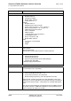
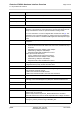
Cinterion® EHS6-A Hardware Interface Overview Page 8 of 40 1.1 Key Features at a Glance 10 Feature Implementation Microsoft™ compatibility RIL for Pocket PC and Smartphone SIM Application Toolkit SAT Release 99 Firmware update Generic update from host application over ASC0 or USB modem. Interfaces Module interface Surface mount device with solderable connection pads (SMT application interface).
Cinterion® EHS6-A Hardware Interface Overview Page 9 of 40 1.1 Key Features at a Glance 10 Feature Implementation Special features Real time clock Timer functions via AT commands Phonebook SIM and phone TTY/CTM support Integrated CTM modem Evaluation kit Evaluation module EHS6-A module soldered onto a dedicated PCB that can be connected to an adapter in order to be mounted onto the DSB75.
Cinterion® EHS6-A Hardware Interface Overview Page 10 of 40 1.2 EHS6-A System Overview 10 1.
Cinterion® EHS6-A Hardware Interface Overview Page 11 of 40 2 Interface Characteristics 22 2 Interface Characteristics EHS6-A is equipped with an SMT application interface that connects to the external application. The SMT application interface incorporates the various application interfaces as well as the RF antenna interface. 2.1 Application Interface 2.1.1 USB Interface EHS6-A supports a USB 2.0 High Speed (480Mbit/s) device interface that is Full Speed (12Mbit/s) compliant.
Cinterion® EHS6-A Hardware Interface Overview Page 12 of 40 2.1 Application Interface 22 2.1.2 Serial Interface ASC0 EHS6-A offers an 8-wire unbalanced, asynchronous modem interface ASC0 conforming to ITU-T V.24 protocol DCE signalling. The electrical characteristics do not comply with ITU-T V.28. The significant levels are 0V (for low data bit or active state) and 1.8V (for high data bit or inactive state). EHS6-A is designed for use as a DCE.
Cinterion® EHS6-A Hardware Interface Overview Page 13 of 40 2.1 Application Interface 22 2.1.3 Serial Interface ASC1 Four EHS6-A GPIO lines can be configured as ASC1 interface signals to provide a 4-wire unbalanced, asynchronous modem interface ASC1 conforming to ITU-T V.24 protocol DCE signalling. The electrical characteristics do not comply with ITU-T V.28. The significant levels are 0V (for low data bit or active state) and 1.8V (for high data bit or inactive state).
Cinterion® EHS6-A Hardware Interface Overview Page 14 of 40 2.1 Application Interface 22 2.1.4 UICC/SIM/USIM Interface EHS6-A has an integrated UICC/SIM/USIM interface compatible with the 3GPP 31.102 and ETSI 102 221. This is wired to the host interface in order to be connected to an external SIM card holder. Five pads on the SMT application interface are reserved for the SIM interface. The UICC/SIM/USIM interface supports 3V and 1.8V SIM cards.
Cinterion® EHS6-A Hardware Interface Overview Page 15 of 40 2.1 Application Interface 22 The figure below shows a circuit to connect an external SIM card holder. V180 CCIN CCVCC SIM 220nF 1nF CCRST CCIO CCCLK Figure 5: External UICC/SIM/USIM card holder circuit The total cable length between the SMT application interface pads on EHS6-A and the pads of the external SIM card holder must not exceed 100mm in order to meet the specifications of 3GPP TS 51.
Cinterion® EHS6-A Hardware Interface Overview Page 16 of 40 2.1 Application Interface 22 2.1.7 GPIO Interface EHS6-A offers a GPIO interface with 22 GPIO lines. The GPIO lines are shared with other interfaces or functions: Fast shutdown (see Section 2.1.14), status LED (see Section 2.1.13), the PWM functionality (see Section 2.1.11), an pulse counter (see Section 2.1.12), ASC0 (see Section 2.1.2), ASC1 (see Section 2.1.3), an SPI interface (see Section 2.1.9), an HSIC interface (see Section 2.1.
Cinterion® EHS6-A Hardware Interface Overview Page 17 of 40 2.1 Application Interface 22 2.1.8 I2C Interface I2C is a serial, 8-bit oriented data transfer bus for bit rates up to 400kbps in Fast mode. It consists of two lines, the serial data line I2CDAT and the serial clock line I2CCLK. The module acts as a single master device, e.g. the clock I2CCLK is driven by the module. I2CDAT is a bi-directional line.
Cinterion® EHS6-A Hardware Interface Overview Page 18 of 40 2.1 Application Interface 22 2.1.11 PWM Interfaces The GPIO6 and GPIO7 interface lines can be configured as Pulse Width Modulation interface lines PWM1 and PWM2. The PWM interface lines can be used, for example, to connect buzzers. The PWM1 line is shared with GPIO7 and the PWM2 line is shared with GPIO6 (for GPIOs see Section 2.1.7). GPIO and PWM functionality are mutually exclusive. 2.1.
Cinterion® EHS6-A Hardware Interface Overview Page 19 of 40 2.2 RF Antenna Interface 22 2.2 RF Antenna Interface The RF interface has an impedance of 50. EHS6-A is capable of sustaining a total mismatch at the antenna line without any damage, even when transmitting at maximum RF power. The external antenna must be matched properly to achieve best performance regarding radiated power, modulation accuracy and harmonic suppression.
Cinterion® EHS6-A Hardware Interface Overview Page 20 of 40 2.2 RF Antenna Interface 22 2.2.1 Antenna Installation The antenna is connected by soldering the antenna pad (ANT_GSM, i.e., pad #59) and its neighboring ground pads (GND, i.e., pads #58 and #60) directly to the application’s PCB. The antenna pad is the antenna reference point (ARP) for EHS6-A. All RF data specified throughout this document is related to the ARP.
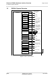
Cinterion® EHS6-A Hardware Interface Overview Page 21 of 40 2.3 Sample Application 22 2.3 Sample Application Figure 6 shows a typical example of how to integrate a EHS6-A module with an application. Usage of the various host interfaces depends on the desired features of the application. The analog audio interface demonstrates the balanced connection of microphone and earpiece. This solution is particularly well suited for internal transducers.
Cinterion® EHS6-A Hardware Interface Overview Page 22 of 40 2.3 Sample Application 22 VDDLP Main Antenna GND RF OUT AUTO_ON / ON GND EMERG_RST 100k RESET BATT+RF BATT+BB VDDLP 150 µF, Low ESR! 53 204 Power supply 50 µF, Low ESR! V180 PWR_IND 33pF VCORE 33pF 22k 100k VMIC 4.7k FB* EHS6-A Mic rophone feeding 100nF 100k MICP MICN Blocking** Blocking** 4 4 8 3 2 GPIO20...GPIO23/ PCM (DAI) HSIC LPM/ GPIO16...
Cinterion® EHS6-A Hardware Interface Overview Page 23 of 40 3 Operating Characteristics 24 3 Operating Characteristics 3.1 Operating Modes The table below briefly summarizes the various operating modes referred to throughout the document. Table 4: Overview of operating modes Mode Function Normal GSM / operation GPRS / UMTS / HSPA SLEEP Power saving set automatically when no call is in progress and the USB connection is suspended by host or not present and no active communication via ASC0.
Cinterion® EHS6-A Hardware Interface Overview Page 24 of 40 3.2 Power Supply 24 3.2 Power Supply EHS6-A needs to be connected to a power supply at the SMT application interface - 2 lines BATT+, and GND. There are two separate voltage domains for BATT+: • BATT+BB with a line for the general power management. • BATT+RF with a line for the GSM power amplifier supply. Please note that throughout the document BATT+ refers to both voltage domains and power supply lines - BATT+BB and BATT+RF.
Cinterion® EHS6-A Hardware Interface Overview Page 25 of 40 4 Mechanical Dimensions, Mounting and Packaging 26 4 Mechanical Dimensions, Mounting and Packaging 4.1 Mechanical Dimensions of EHS6-A Figure 7 shows the top and bottom view of EHS6-A and provides an overview of the board's mechanical dimensions. For further details see Figure 8. Product label Top view Bottom view Figure 7: EHS6-A– top and bottom view EHS6-A_HIO_v04.
Cinterion® EHS6-A Hardware Interface Overview Page 26 of 40 4.1 Mechanical Dimensions of EHS6-A 26 Figure 8: Dimensions of EHS6-A (all dimensions in mm) EHS6-A_HIO_v04.
Cinterion® EHS6-A Hardware Interface Overview Page 27 of 40 5 Regulatory and Type Approval Information 33 5 Regulatory and Type Approval Information 5.1 Directives and Standards EHS6-A is designed to comply with the directives and standards listed below.
Cinterion® EHS6-A Hardware Interface Overview Page 28 of 40 5.1 Directives and Standards 33 Table 7: Standards of European type approval ETSI EN 301 908-1 V11.1.1 IMT cellular networks; Harmonised Standard covering the essential requirements of article 3.2 of the Directive 2014/53/EU; Part 1: Introduction and common requirements ETSI EN 301 908-2 V11.1.2 IMT cellular networks; Harmonised Standard covering the essential requirements of article 3.
Cinterion® EHS6-A Hardware Interface Overview Page 29 of 40 5.1 Directives and Standards 33 Table 10: Toxic or hazardous substances or elements with defined concentration limits EHS6-A_HIO_v04.
Cinterion® EHS6-A Hardware Interface Overview Page 30 of 40 5.2 SAR requirements specific to portable mobiles 33 5.2 SAR requirements specific to portable mobiles Mobile phones, PDAs or other portable transmitters and receivers incorporating a GSM module must be in accordance with the guidelines for human exposure to radio frequency energy.
Cinterion® EHS6-A Hardware Interface Overview Page 31 of 40 5.3 Reference Equipment for Type Approval 33 5.
Cinterion® EHS6-A Hardware Interface Overview Page 32 of 40 5.4 Compliance with FCC and ISED Rules and Regulations 33 5.4 Compliance with FCC and ISED Rules and Regulations The Equipment Authorization Certification for the Gemalto M2M reference application described in Section 5.
Cinterion® EHS6-A Hardware Interface Overview Page 33 of 40 5.4 Compliance with FCC and ISED Rules and Regulations 33 Notes (ISED): (EN) This Class B digital apparatus complies with Canadian ICES-003 and RSS-210. Operation is subject to the following two conditions: (1) this device may not cause interference, and (2) this device must accept any interference, including interference that may cause undesired operation of the device.
Cinterion® EHS6-A Hardware Interface Overview Page 33 of 40 6 Document Information 37 6 Document Information 6.1 Revision History Preceding document: "Cinterion® EHS6-A Hardware Interface Overview" Version 02.770 New document: "Cinterion® EHS6-A Hardware Interface Overview" Version 04.000 Chapter What is new 1.1; 2.1.2; 2.1.3 Update the bit rate range for ASC0 and ASC1 5.1 Update Table 6 and Table 7 regarding versions of standards. 7.1 Update Table 11 regarding ordering numbers 5.
Cinterion® EHS6-A Hardware Interface Overview Page 34 of 40 6.3 Terms and Abbreviations 37 Abbreviation Description BTS Base Transceiver Station CB or CBM Cell Broadcast Message CE Conformité Européene (European Conformity) CHAP Challenge Handshake Authentication Protocol CPU Central Processing Unit CS Coding Scheme CSD Circuit Switched Data CTS Clear to Send DAC Digital-to-Analog Converter DAI Digital Audio Interface dBm0 Digital level, 3.
Cinterion® EHS6-A Hardware Interface Overview Page 35 of 40 6.
Cinterion® EHS6-A Hardware Interface Overview Page 36 of 40 6.3 Terms and Abbreviations 37 Abbreviation Description RoHS Restriction of the use of certain hazardous substances in electrical and electronic equipment.
Cinterion® EHS6-A Hardware Interface Overview Page 37 of 40 6.4 Safety Precaution Notes 37 6.4 Safety Precaution Notes The following safety precautions must be observed during all phases of the operation, usage, service or repair of any cellular terminal or mobile incorporating EHS6-A. Manufacturers of the cellular terminal are advised to convey the following safety information to users and operating personnel and to incorporate these guidelines into all manuals supplied with the product.
Cinterion® EHS6-A Hardware Interface Overview Page 38 of 40 7 Appendix 39 7 Appendix 7.
Cinterion® EHS6-A Hardware Interface Overview Page 39 of 40 7.1 List of Parts and Accessories 39 Table 12: Molex sales contacts (subject to change) Molex For further information please click: http://www.molex.com Molex Deutschland GmbH Otto-Hahn-Str. 1b 69190 Walldorf Germany Phone: +49-6227-3091-0 Fax: +49-6227-3091-8100 Email: mxgermany@molex.com American Headquarters Lisle, Illinois 60532 U.S.A.
40 About Gemalto Since 1996, Gemalto has been pioneering groundbreaking M2M and IoT products that keep our customers on the leading edge of innovation. We work closely with global mobile network operators to ensure that Cinterion® modules evolve in sync with wireless networks, providing a seamless migration path to protect your IoT technology investment.