
Specifications
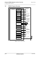
Table Of Contents
- Contents
- Tables
- Figures
- 1 Introduction
- 2 Interface Characteristics
- 2.1 Application Interface
- 2.1.1 USB Interface
- 2.1.2 Serial Interface ASC0
- 2.1.3 Serial Interface ASC1
- 2.1.4 UICC/SIM/USIM Interface
- 2.1.5 Analog Audio Interface
- 2.1.6 Digital Audio Interface
- 2.1.7 GPIO Interface
- 2.1.8 I2C Interface
- 2.1.9 SPI Interface
- 2.1.10 HSIC Interface
- 2.1.11 PWM Interfaces
- 2.1.12 Pulse Counter
- 2.1.13 Status LED
- 2.1.14 Fast Shutdown
- 2.2 RF Antenna Interface
- 2.3 Sample Application
- 2.1 Application Interface
- 3 Operating Characteristics
- 4 Mechanical Dimensions, Mounting and Packaging
- 5 Regulatory and Type Approval Information
- 6 Document Information
- 7 Appendix

Cinterion
®
EHS6-A Hardware Interface Overview
Figures
111
EHS6-A_HIO_v04.000 2019-03-05
Confidential / Preliminary
Page 5 of 40
Figures
Figure 1: EHS6-A system overview............................................................................... 10
Figure 2: USB circuit ..................................................................................................... 11
Figure 3: Serial interface ASC0..................................................................................... 12
Figure 4: Serial interface ASC1..................................................................................... 13
Figure 5: External UICC/SIM/USIM card holder circuit ................................................. 15
Figure 6: Schematic diagram of EHS6-A sample application........................................ 22
Figure 7: EHS6-A– top and bottom view....................................................................... 25
Figure 8: Dimensions of EHS6-A (all dimensions in mm) ............................................. 26
Figure 9: Reference equipment for Type Approval ....................................................... 31