THALES NAVIGATION MobileMapper User Manual www.thalesnavigation.
Table of Contents Introduction to the MobileMapper System......................................................... 1 MobileMapper Field Unit............................................................................3 Keypad Description ............................................................................................ 3 Installing the Batteries .................................................................................. 4 Turning Power On/Off ................................................
Creating a Multi-leg Route.......................................................................................43 Creating a Multi-leg Route from the Track History.................................................44 Activating/deactivating a Multi-Leg Route..............................................................44 Other Functions Tied to Routes................................................................................45 MENU button ...............................................................
Defining Feature Attributes ........................................................................ 80 Defining Attribute Values ........................................................................... 81 Renaming a Feature, Defining its Representation on the Map ................... 82 Deleting Features, Attributes or Attribute Values ...................................... 83 Saving a Feature Library.............................................................................
iv
Introduction to the MobileMapper System The MobileMapper system from Thales Navigation is composed of two main elements: the MobileMapper receiver and MobileMapper Office software running on a PC-type computer. The MobileMapper receiver is a handheld navigation and positioning device that enables you to describe the features being mapped and then format the data so that later it can be uploaded to a GIS. It offers an easy-to-use and easy-to-deploy solution for general mapping and for asset management.
2
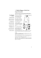
1. MobileMapper Field Unit Keypad Description Under the screen you will see 8 buttons located around a large oval “scrolling” button with 4 directional arrows on it. The scrolling button has three different functions: • It is used to move the cursor in the chosen direction, from a data field to another, from an option in a menu to the previous or next option.
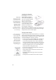
Installing the Batteries Battery Life You can expect up to 16 operating hours from 2 Li-ion AA batteries with the backlight turned off. Using the backlight will shorten the battery life significantly. With the backlight on continuously, you can expect about up to 8 hours of usage from the two Li-ion batteries that came with your MobileMapper. MobileMapper uses two AA batteries that are installed from the back through the battery cover.
Setting the Screen Backlight To prevent accidently turning the backlight on and leaving it on, the unit will turn the backlight off when there have been no buttons pressed for 4 minutes. Pressing any button will turn the backlight back on in this instance. You can change the time delay for the backlight using the Light Timer option in the Setup menu (see page 56). The screen backlight can be set to one of three levels (low, high or off). At power on, the screen backlight is set to high level.
Initialization for First-Time Use Skipping Initialization You can skip the initialization process by pressing the NAV key anytime after selecting the language you want MobileMapper to use and accepting the agreement. If MobileMapper is able to collect satellite data (i.e., have a clear view of the sky) it will begin to self-initialize. This could take anywhere from 3 to 14 minutes to compute its position, depending on how many weeks have elapsed since it was last used.
3. If you understand and agree to the warning presented, press ENTER before the 10 seconds have elapsed. Otherwise, the unit will shut off. A message box is then displayed indicating that the unit needs to be initialized. Region & Area Screens 4. Press ENTER. The unit asks you to select your region and area. Use the up/down arrows to highlight your general region and press ENTER. Again, use the up/down arrows to highlight your area and press ENTER. 5.
Satellite Signal Strength Chart: Clear bars indicate that the unit is starting to get information from satellites. Solid bars indicate that the satellites are being used to compute your position. Satellite Position Graph: The 2 circles indicate satellite elevation as seen from your current position. The outer circle represents the horizon and the inner circle represents 45° from the horizon. The center of the circle is 90° from the horizon, or directly overhead. 8 6.
GIS Data Logging Functions Feature Libraries A feature library is a hierarchical structure that guides you through the description process so you know you will describe thoroughly and quickly each feature you visit.
Logging New GPS/GIS Data Prior to starting logging GIS data, be sure MobileMapper is computing your position when you stand near the first feature you want to log. Press NAV until you display the Map screen. If an arrow is displayed at the center of the Map screen and you can see that your position on the screen is the expected one, then you can start your job. Follow the instructions below to log GIS features.
- Logging screen The Logging screen also displays the time elapsed since you started logging at this point feature, the number of satellites currently received and the current value of PDOP (see also page 22). If you start logging a new feature and you realize you this is a mistake, then you can delete the new feature being logged by pressing MENU and selecting Delete . Deleting features only applies to new features being logged, not to features already logged.
Selecting the logging interval option Logging screen The Logging screen also displays the distance traveled since you started logging the line feature, the number of satellites currently received and the current value of PDOP (see also page 22). 12 After highlighting a line feature from the Feature List screen (for example a road) and pressing ENTER, MobileMapper starts logging GPS positions from the position where you are.
Irregular area Regular area Logging screen The Logging screen also displays the current value of area measured since you started logging the feature, the number of satellites currently received and the current value of PDOP (see also page 22). 4. Logging and Describing an Area Feature Basically, you use the same procedure as when you log a line feature, especially regarding the need for defining a logging interval (see 3. above).
Selecting the Pause Park option - Selecting the Repeat Feature option 14 By the time you are done with the description, MobileMapper will probably have logged the GPS position of the corner. Now, press MENU, highlight Pause and press ENTER. This pauses the logging of the feature. Move to the next corner of the area where you can now resume logging the feature To do this, press MENU, highlight Resume and press ENTER. This resumes the logging.
6. Nesting a Feature When you are logging GPS positions to a feature, you may find another feature that you also want to log. Rather than log the entire feature and come back to record this other feature, you can simply pause the feature being logged, log the other feature, close it and resume logging the first feature. Logging one feature while you have paused another feature is called “nesting.” You can nest any feature, point line or area, into any line or area feature.
Point Offset screen If you do not have a compass, you can use MobileMapper’s Compass screen (see also page 31) to determine the bearing to the offset feature. If you have been moving for 5 to 10 seconds along a straight line, the Compass screen will tell you your bearing. You can use this to determine the bearing to the offset feature. CAUTION! The receiver cannot determine direction while stationary. Visual estimation for horz. & vert. distances is usually good enough in terms of accuracy. 16 7.
Line or Area Offset screen Line On the left Area On the right Visual estimation for horz. & vert. distances is usually good enough in terms of accuracy. 8. Offsetting a Line or Area Feature For the same reasons as a point feature (see previous page), you may need to use the offset utility to map a line or area feature. By combining the receiver’s position with the direction and the distance to the feature, MobileMapper will automatically calculate and record the location of the feature.
To operate the grid mapping utility, you will need a measurement device anything from a depth sounder to a ruler, your own sense of smell or your ability to make visual observations. You will also need a compass. North Heading Column Spacing Row How a grid is defined in MobileMapper 18 9. Logging GIS Data on a Preset Grid Network MobileMapper's grid mapping utility is an easy way to automatically set up a series of GPS waypoints to facilitate the logging of data in an orthogonal grid.
It is also possible to navigate to any grid waypoint (or any location for that matter) on the Map screen by moving the arrow key over another grid waypoint and pressing ENTER. After you record data at this location, the Next Pt field may still be selected to go to the next grid waypoint in the network. - Record an observation or measurement: With the OK field highlighted, just press ENTER.
Each grid waypoint is a geographic coordinate you should make every effort to occupy so that the data you record is evenly spaced and complete. However, each grid waypoint is merely an aid for navigating to the ideal location for an observation or measurement. All the data you record is ascribed to the position of the MobileMapper receiver and NOT to the grid waypoint.
North Spacing Column Grid Setup screen Row (Heading= 0°) North Heading=21° Column Spacing Row In the two examples above: Columns=8 Rows=6 In the open job, do the following: - On the Feature List screen, select the grid feature and press ENTER. On the Grid Setup screen that is now displayed, set the parameters listed below.
GPS Accuracy MobileMapper is also capable of providing 3-m horizontal accuracy using real-time differential corrections from its built-in WAAS/EGNOS receiver. You must be in North American to make use of the free WAAS signal broadcast by the US Federal Aviation Administration. You must be in Europe to make use of the free EGNOS signal broadcast by the European Union. If you are receiving a WAAS or EGNOS signal, a “W” appears on the screen.
Revisiting and Updating Existing GPS/GIS Jobs You can use MobileMapper not only to position and describe new GIS features but also to update information gathered previously. This is particularly useful when collecting data on things that change over time: streetlight bulbs burn out, new roads are added to housing developments, new crops are planted, etc. 1.
Map screen showing straight line to target 24 - Press ENTER to ask MobileMapper to guide you to this feature. If you simply press ENTER, you will make the selected feature your destination and all the navigation screens will be set to help you reach that feature. Press NAV to access any of these screens. On the Map screen, you can now see a straight line connecting your current destination to the selected feature. - Walk to the feature according to the navigation instructions provided on the Map screen.
The Repositioning function only applies to point features, not to line or area features. Selecting Update Position 2. Repositioning a Point Feature If a point feature appears to be mislocated on the Map screen or if you wish to make the position more accurate (by using an external antenna, occupying point positions for more time, etc.
The Map screen has two modes: Position and Cursor. Use any arrow key to select Cursor mode, ESC to return to Position mode When a Position screen is displayed, press the Left or Right arrow key to display the other. Press this key again to return to the previous screen. Except for the Satellite Status screen, all navigation screens can be customized.
The dotted line on the map displays the history of where you have traveled since the last time you cleared the track history. Press any of the arrow keys to switch to the Cursor mode. In this mode, you are provided with a cross hair cursor that can be moved on the map with the arrow keys. At the bottom of the display is the information for the position of the cursor relative to your present position (heading and distance). Also any points of interest or GIS features that the cursor is over will be shown.
Select Map Info Use this option to tell MobileMapper which data should be displayed at the bottom of the Map screen. This can be: The Map screen must be in Position mode if you wish to customize data fields. If the Map screen is in cursor mode (cursor is a cross-hair), press ESC to return to the Position mode - Customize Fields. This function is equivalent to the Customize function available from all navigation screens other than the Map screen. See page 38.
Track Mode, Fixed Rate Track Mode, Auto Track Mode, Auto Detailed - Track Mode: Allows you to set how often MobileMapper stores track points. Setting the mode to Off stops the unit from saving any new track points. With Auto or Auto Detailed enabled, MobileMapper uses a method for track point storage that maximizes memory. Using Auto, you will see more points on and near turns and less points on straight stretches of the map. You also have the option of selecting fixed intervals for track point storage.
Check the items you want to show and clear those you want to hide. You can also check or clear all these items in a single operation by respectively selecting Mark All or Clear All just above these items and then pressing ENTER Goto Cursor If the Map screen is in cursor mode, the first option available from the list displayed after pressing the MENU button is Goto Cursor. Select this function when you want MobileMapper to guide you to the location where the cursor currently is on the Map screen.
Compass Screen The two data fields on top are customizable. The lower portion of the Compass screen not only displays your heading in a graphical manner, but also displays the relationship of the sun, moon and your destination (if navigating on a route) to your heading. The Compass screen contains the following information, from top to bottom: Compass Screen - In the title bar: destination name if you are using the Goto function - Data Fields: customizable data fields (see Customize option below).
Large Data Screen The Large Data screen is similar to the Compass screen but here the compass has been removed to allow for large display of the navigation data. This screen is ideal for when you have your unit mounted on the dashboard of a vehicle. Even from a distance the customizable information can be read with ease.
Position Screens Position screens #1 and #2 display your present position using the coordinate systems that you have selected. This screen shows all of the basic position, time and satellite information. Additionally, on Position screen #1, current navigation information is shown in the bottom half of the screen.
- Data Fields: customizable data fields (see Customize option below). Some of the data displayed requires you to be moving to be computed. Invalid data is indicated by dashes. - Trip Odometer: The odometer performs like the odometer in your car. It can be reset through the MENU button. To customize the Position screens, use the functions described below. The first of these context-sensitive functions is prompted when you press the MENU button while a Position screen is displayed.
Road Screen The Road screen presents your route as if you were travelling on a road. When you need to make a turn, the road will graphically display the turn and the direction. Waypoint and destination icons will be displayed relative to your position as they come into view. Above the road is a compass that displays your heading and above that are four customizable data fields.
Data Screen When you need to see a lot of information in one place then you will appreciate the Data screen. The Data screen provides you with six data fields and an active compass that is the same as the one used on the road screen. You have the option of customizing this screen by selecting what data is displayed in the upper six fields. The lower portion of the screen is occupied by a compass providing your heading.
Speedometer Screen The Speedometer screen displays your speed in a familiar graphical format. There are four additional data fields at the top of the display that can be customized to display the data that you need. The bottom of the screen contains a trip odometer that will record the distance travelled since the last time the odometer was reset.
Satellite Status Screen Although the Satellite Status screen is part of the navigation screen sequence, it is not actually a navigation screen. For more details on this screen, refer to page 8. Satellite Status Screen When MobileMapper is computing your position, an additional information appears in the right-upper corner with two possible values: 3D or 2D. 3D means the computed position is 3-dimensional (elevation computed). In 2D (2-dimensional), elevation is not computed.
GOTO Function Purpose You will use the Goto function to ask MobileMapper to guide you from your current position to a destination point. After you will have specified which destination point to go to, you will select your favorite navigation screen. You will then be able to read the information computed by MobileMapper to help you reach the destination. Destination Point Types Not only can MobileMapper guide you to previously logged GIS features but also to other pre-loaded or created points.
Selecting a POI as the Destination Point Press MENU, scroll to the GOTO option and press ENTER. The possible categories of POIs are now listed on the screen. Select the category the destination point belongs to. Before pressing ENTER to list all the points stored in this category, choose how you want these points to be listed by setting the Find By field. Press the left/right arrow to set this field.
Saving Your Current Position as a Waypoint Saving your current position as a waypoint is very easy and can be done regardless of whether a GIS job is open or not. From any navigation screen, just hold down the LOG button for 2 to 3 seconds until the Mark screen is displayed. This screen provides the description of the waypoint you are about to save.
Editing/Deleting a User Waypoint You can edit/delete a waypoint from the Map screen: Select Item screen User Waypoint screen 42 - Press NAV until the Map screen is displayed - Use the IN or OUT button, or move the cursor so that the waypoint you want to edit or delete is visible on the screen - Position the cursor over that waypoint. The name of the waypoint then appears at the bottom of the screen. - Press ENTER.
Routes As explained below, MobileMapper can handle two types of routes: GOTO route and multi-leg route. GOTO Route This in fact a route that you define when: A GOTO route is a oneleg route whose two ends are your current position and the chosen destination point. - You select a feature on the Map screen, you press ENTER to display the attributes of this feature, and you press ENTER again to enable the Goto function to this feature (by default, the Goto field at the bottom of the screen is highlighted).
The Create Route screen is now displayed. Note that the first line on this screen is highlighted. Press ENTER. The Add WPT screen is now displayed. Select the category of points containing the first waypoint of the route and press ENTER. Choose a point from the list and press ENTER. The first waypoint in the route is now defined and you are now prompted to define the second one. Resume the instructions in this paragraph for the second point, then for the third, etc.
4. Other Functions Tied to Routes You can also do the following on the highlighted route using the functions available from the MENU button (see also diagram on page 49): - Viewing the route on the Map screen by highlighting the Map View Route option and pressing ENTER. The Map screen then appears showing the route. Press ESC to come back to the Route List screen. - Editing the route by highlighting the View/Edit Route option and pressing ENTER.
MENU button In the previous chapters, we have introduced most of the context-sensitive functions available from the menu list. In fact, these functions are closely tied to MobileMapper’s main functionality (GIS data logging and navigation). In this chapter, we present the supplemental functions. The list of functions that you can have access to by pressing the MENU button depends on which navigation screen is displayed and whether GIS data logging is in progress or not.
The second diagram shows the available functions when pressing MENU when a GIS job is open and one of the GIS logging-specific screens is displayed. Line or area feature being logged Point feature being logged From feature list screen (Repeat Feature) Close Job Repeat Feature Offset Close Delete Pause/Resume Repeat Feature Offset Close Nest Feature Logging Interval Delete Mark GOTO Routes Setup Delete Files About...
Open Job This option provides another way of opening a GIS job. It is similar to selecting the Open Existing Job option that is prompted on the screen after pressing the LOG button when no job is open yet. Selecting this option when a job is already open allows you to close the currently open job and open another one. New Job This option provides another way of creating a new GIS job.
GOTO This option is discussed in detail on page 39. Routes This option is discussed in detail on page 43. The MENU button gives access to a list of specific options when the Routes option is enabled. This is summarized in the diagram below.
Change Map screen 2. Select Map This option is mainly used to choose the base map used as background map on the Map screen. The following parameters can be set on the Change Map screen: - Basemap: If no SD card containing a specific map is installed in MobileMapper, then only the Default Map option can be selected in this field. The default map is always present in MobileMapper.
Default coordinate systems: Primary: Lat/Lon Secondary: UTM 5. Coord System This option allows you to define a primary coordinate system, and also a secondary coordinate system if you need one. By defining a coordinate system, you tell MobileMapper how the calculated coordinates should be expressed.
Default Map datums Primary: WGS84 Secondary: WGS84 Default Elev mode: 3D 52 6. Map Datum This option allows you to define a primary map datum, and also a secondary map datum if you need one. A map datum is a geographic reference that MobileMapper will refer to to calculate the coordinates of your position. MobileMapper holds more than 70 different map datums in its memory.
Default time format: Local AM/PM Default units: km/m/kph/ hectares 8. Time Format This option allows you to select the time format you want to use in MobileMapper. You can choose from three different time formats: Local 24Hrs, Local AM/PM or UTC. After selecting the Time Format option from the Setup menu, choose the time format that suits you and then press ENTER. If you have selected Local 24 Hrs or Local AM/PM, you will be prompted to enter your local time. 9.
Alarms menu 10.Alarms All of the Alarm options are set in the same way. The instructions below apply to all of the Alarm settings. When the beeper is turned on for alarms (see Beeper option) an audible beep will be sounded for the alarm. A visual alert is displayed for the alarm whether the beeper is turned on or off. Setting the Arrival Alarm: The arrival alarm alerts you that you have arrived at the destination of your GOTO route or to the destination of any leg in a route you are navigating on.
Default North Reference: True Default: The appropriate daylight saving time (United States and European Union only) will automatically be set during startup when you use mobileMapper for the first time. 11.North Reference This option allows you to define the type of North reference you want MobileMapper to use. This can be True North, Magnetic North, Military True North or Military Magnetic North.
Default: Off It’s a good idea to use this option when you transport your MobileMapper unprotected in a bag. This will prevent the batteries from being entirely discharged after the PWR button has been inadvertently depressed. 13.Power Off Timer Conserving battery life is important to any handheld GPS user. The Power Off Timer option provides another tool in saving battery life. Selecting On will allow you to select the mode and how long MobileMapper will stay powered on.
16.Beeper This option allows you to select which actions will cause the beeper to sound. You can select one of the following choices: - Off (beeper will never sound) - Keys Only (pressing a key causes a beep) - Alarms Only (when an alarm is activated) - Keys & Alarms (beeper will sound when a key is pressed or an alarm is activated) After selecting the Beeper option from the Setup menu, use the up/down arrow to highlight the desired choice and then press ENTER. 17.
18.NMEA This option allows you to select the NMEA message that will be output from MobileMapper. Your choice will depend on which message is needed by the device connected to MobileMapper: - V1.5 APA: Autopilot Sentence “A” - V1.5 XTE: Crosstrack error according to NMEA0183 V1.5 - V2.1 GSA: Standard GPS position message according to NMEA0183 standard in version 2.1 After selecting the NMEA option from the Setup menu, use the up/down arrow to highlight the desired choice and then press ENTER. 19.
Default: No protection 20.Power Key This option allows you to change how the PWR button operates in turning MobileMapper on or off. Two choices are possible: - No protection: this is the normal case of use. With this option enabled, you will have to press the PWR button to turn MobileMapper on. You will press the PWR button again to turn MobileMapper off. - On/Off protected: To turn MobileMapper on with this option enabled, you will have to press and hold the PWR button until the first screen is displayed.
After selecting the Simulate option from the Setup menu, use the up/down arrow to highlight the desired choice and then press ENTER. If you have selected User, MobileMapper will then ask you to enter heading and speed data. A message will then appear warning you that enabling the simulator will necessarily clear track history. Make the appropriate choice. If you have selected Auto, MobileMapper will also display the warning message about track history. 22.
Delete Files This option allows you to list the job files stored in memory. Use the up/down arrow to scroll through the list. A symbol is placed before each filename. The meaning of this symbol is as follows: > Indicates that this file is the current file into which data is being recorded + Indicates that the file has not yet been downloaded from the handheld - Indicates that the file has been downloaded from the handheld.
62
2. MobileMapper Office Software Introduction The functions supported by MobileMapper Office are listed below: Conventions used for directions of data transfer Upload Download - Creating Job files. A job should always contain a feature library. The name of the coordinate system selected in the program is also automatically attached to the job.
- Creating background maps using the Background Map and Create Map utilities. When you create a background map, you can import SHP, DXF or MIF files to add useful details to your map. Remember however that background maps are for viewing only. You cannot edit them or access information on their features. They provide a backdrop, which gives visual orientation for your data and waypoint files.
MobileMapper Office Main Window Map Display area Layer List The main window of MobileMapper Office is organized as explained below (see also above figure): - The Map Display area runs from the bottom of the Menu bar to the bottom border. It takes up about two-thirds of the screen, right to left.
Map Display Area Controlling the Content of the Map Display Area The data displayed in the Map Display area is controlled by the Layers List shown on the right-hand area of the main window. When you want one of the listed layers displayed in the Map Display area, just fill in the check box located before this layer name. As a result, all the items pertaining to this layer will be shown in the Map Display area.
Below is the list of buttons from the Map toolbar that you can use to work on the content the Map Display area: : Allow you to respectively zoom in, zoom out and fit the scale to the map content : Allows you to adjust the scale to preset values : Allows you to drag the map in any direction. : Allows you to select the map of a continent for display in the Map Display area as a backdrop to the job data (and also to the background map itself, if displayed).
Making Measurements on the Map Display Area You can measure the distance and heading between any points displayed in the Map Display area: - On the toolbar, click , then click on the point on the map from which to start the measurement. The start point is then marked with a small square symbol.
Working on Job Files Creating a New Job Before you ask field operators to create a new job, you just need to create the appropriate feature library and upload it to their handhelds. Field operators will then just have to create a new job based on this feature library. But you can also prepare an “empty” job using the procedure below and ask field operators to open that job for their field operations. By “empty job” we mean “with no features logged yet in the job.
Connecting the Handheld to the PC - Connect the MobileMapper handheld to one of the serial ports on your office PC using the serial cable provided with the handheld - If you are connecting the handheld to the PC for the first time, do the following: • On the menu bar, select Options and then GPS Settings... • In the dialog box that opens, click Autodetect. MobileMapper then starts a sequence to determine the port that MobileMapper is connected to, as well as the baud rate used on the receiver side.
Uploading a Job to the Handheld First of all, you have to connect the handheld to the PC running MobileMapper Office and test the connection, as explained in the previous chapter. You must make sure that the SD card is inserted into the receiver to ensure proper data transfer between the handheld and MobileMapper Office - Open the file job in MobileMapper Office using the File>Open command. Job filenames are in the form “*.mmj”.
Downloading a Completed Job from the Handheld MobileMapper Office uses the MobileMapper Transfer utility as an interface program to access the files stored on the MobileMapper handheld. First of all, you have to connect the handheld to the PC running MobileMapper Office and test the connection, as explained on page 70. - On the menu bar, select File>Download from GPS. This opens the MobileMapper Transfer window on your screen. The right-hand pane lists all the files present in the default directory (...
After a while, the window’s left-hand pane should list the content of the handheld’s memory. Downloading a job always includes importing the downloaded data to the open job, unless the downloaded data is not based on the same feature library as the open job. 1. Downloading a job file - Drag and drop this file from the left-hand pane to the right-hand pane. - Close the MobileMapper Transfer window.
Viewing the Content of a Job After downloading a completed job in MobileMapper Office as explained in the previous chapter, you can also open it in MobileMapper Office using the File>Open command. As a result, MobileMapper Office shows the content of this job in the main window. First of all, you can see the list of layers present in this job in the right-hand part of the screen. Clear or check the buttons for the layers you want to see in the Map Display area.
Exporting Jobs in GIS Formats The most important processing of your field data is its export to a GIS. Exporting field data has two processes: conversion of the data files to a standard format a GIS can read and then the actual transfer of the file. To convert your data into SHP, MIF or DXF: Exporting to DXF requires that a grid system be used in the job Note that you can also export a job to the MMF format.
Using the Feature Library Editor Introduction Note the following limits for feature libraries: No. of feature types: 15 max. No. of attributes per feature: 10 max. No. of attributes values per Menu-style attribute: 5 max. MobileMapper Office allows you to create new feature libraries using the Feature Library Editor. Feature libraries are used by field operators as a common basis for describing the features they visit in the field.
There are four different types of features: Point feature - Point feature: This feature can be described as a point, geometrically speaking. Field operators should log point features in static mode, i.e. they are supposed to stay stationary at these points for at least one second. Line feature - Line feature: This feature can be described as a line. Field operators should log line features in kinematic mode, i.e.
Creating a New, Standalone Feature Library File - On the menu bar, select Tools, then Feature Library Editor. This opens the Feature Library Editor window at the center of the screen. Warning! If a job is open in MobileMapper Office’s main window, the Feature Library Editor window then shows the feature library used in the open job. This library cannot be changed. That’s why you have to do the following. - On the menu bar, select File, then Save As...
Inserting New Features to the Feature Library - In the Feature Library Editor window, right-click on the feature library name and select Insert Feature. A new dialog box opens in which you can define the first feature for the library: It sometimes is a good idea to choose a name that reflects the geometry type of the feature.
Defining Feature Attributes - Under the feature library name, in the left-hand part of the Feature Library Editor window, select the first feature name, right-click on it and select Insert Attribute. A new dialog box opens where you can define the first attribute for the feature: - Enter a name for this attribute in the Attribute Name field - Indicate the type of the attribute. There are three types of attributes: Menu, Numeric and Text.
Defining Attribute Values You define attribute values in the right-hand pane of the Feature library Editor window. - Click on the name of the first attribute of the first feature. The right-hand pane of the Feature Library Editor window now shows a table containing the definition of this attribute. The highlighted cell is where you can enter the first attribute value for this attribute. Click on this cell. - Type in the attribute value and press ENTER on your keyboard.
Renaming a Feature, Defining its Representation on the Map Still from the Feature Library Editor window, you can change the name of a feature as explained below: - In the left-hand pane of the window, click on the feature name you want to edit. This displays the Feature Type table on the right. - Double-click on the cell containing the feature name (see example below) and type in a new name - Press the Enter key to record the change.
The representation of a line or area feature on the map is based on line properties that you can define as explained below: - In the Style/Color/Width row of this table, click . A new dialog box opens in which you can define the properties of the line representing the line feature or the contour of the area feature (color, style and width): Possible choices: 16 for color, 3 for style and 3 for width.
- To delete an attribute value from the list of possible values of a Menu-style attribute, first select the concerned attribute in the left-hand pane of the Feature Library Editor window. Then in the right-hand pane of this window, highlight the cell containing the attribute value you want to delete and press Del on your keyboard. Deletion is immediate as MobileMapper Office does not require user confirmation.
Importing a Feature Library from a Job or GIS File Using the File>Import command in the Feature Library Editor window, you can import the feature library used in an existing job or from a MIF or SHP file.
Grid Mapper Utility Introduction Working with the Grid Mapper Utility is an easy way to log GPS positions and GIS data at waypoints arranged in an evenly spaced grid. This allows you to gather measurements - made by field sensors such as depth sounders, chemical detectors and magnetometers - in an organized fashion with an easy-to-use navigation feature. You can then create contour maps with the necessary density of data while avoiding any gaps that might force you to return to the field. Grid Features vs.
However, line and area features differ from grid features in two important ways: - The positions making up line and area features mark the locations of real things like roads, lakes, etc. But the points making up a grid feature are imaginary target locations that you navigate to. - The attributes you record for a road or a lake pertain equally to each of the point positions making up feature, but you typically record different descriptions at each grid point making up the grid feature.
North Column Name: Feature names like “pole,” “road” or “lake” make it easy to identify the geometry of point line and area features. This is not so easy with grid features. You might find it helpful to insert the word “grid” into the name of grid features. However, there is a 10-character limit to the name length so you may prefer to name the grid types with distinctive names like “mag. field,” “H2O depth” or “CO2 conc.
When changing from the default 50 meters, keep in mind that the selected value will determine the density of measurements. If this number is less than 5 meters or so, there is no point in using a Grid feature. Simply walk around and take samples by visually estimating the required density. If you increase the spacing, be sure the spacing supports the density of measurements you require.
Using the Waypoint/Route Editor Introduction The Waypoint/Route Editor allows you to easily create a list of waypoints that might be useful for the field operator when she/he is performing a GIS job. For example one of these waypoints may help to localize a hardly visible feature. The Waypoint/Route Editor also allows you to build new routes, based on the existing list of waypoints. To save your waypoints and routes, you just need to save the currently open job.
Editing a waypoint Defining the name and icon of the next waypoint - In the right-upper part of the window (see example opposite), you can now make changes to the definition of this waypoint (name, coordinates, icon, optional comment). - Next to this definition area, you can also define the name and icon for the next waypoint you will create - When you are done with the definition of the first waypoint, create the second waypoint by clicking on the map where this second waypoint should be located.
Finding a Waypoint on the Map Use the View function when you have some difficulty finding a waypoint on the map because there are lots of them, or simply because you don’t want to spend too much time searching for it MobileMapper Office helps you locate rapidly a waypoint. - In the waypoint table, right-click on the row containing the definition of the waypoint and select View.
Building a Route After you have created a number of waypoints as explained in the previous chapter, you can now define routes graphically. Follow the instructions below to do this. Creating a four-waypoint route - On the toolbar, click . This opens a new window in the right-upper part of the window where MobileMapper automatically creates a new route named “Route1” (if it’s the first one in the list) (see opposite). Note that MobileMapper Office continues to display the waypoint table below this window.
Background Maps Introduction Background maps are designed to provide useful details on working areas. Field operators might like to see these details on their handheld screens as they progress in their jobs so that they can more easily go to the places they have to visit. Background maps are for viewing only. You cannot edit them or access information on their features. They provide a backdrop, which gives visual orientation for your data and waypoint files.
A background map generally consists of a base map, plus additional details that you can for example import from your GIS system.
Creating a New Background Map Project - On the menu bar, select Tools and then Background Map. This opens the Background Maps window - Click on the Create New... button. This opens the Create Map window from which you can create a new background map project: - Type in a name for the background map project in the Map Name field. - In the Map Scale field, choose a scale value above which the background map will NOT be displayed on the Map Display area or on the handheld screen.
Adding Layers to a Background Map Project (Continued from previous paragraph.) You can add as many layers as necessary to build a background map. Layers may be SHP files or MIF files. For example you could export to SHP ou MIF the features of a completed job and then add them as layers to create a background map. In this case you would merge these features into the background map and so they would no longer be selectable as individual entities on the Map Display area.
Changing the Order of Layers When you build the background map, the first layer you placed in the table will be brought to the front, and the last one will be sent to the back. Intermediate layers will occupy intermediate positions in the layer stack. If one of your layers contains area features, it is important that this layer be placed at the bottom of the table otherwise all layers containing point or line features located within these area features would be hidden by these features.
Changing the Visual Aspect of Layers You can customize each layer by clicking on the corresponding leftmost cell in the table. This opens a dialog box in which you can choose the aspect you want for the layer when the background map is built up later. As you will probably notice, the available options are much similar to those available when creating features with the Feature Library Editor.
- Then click , or on the menu bar, select Operations>Create Map. MobileMapper Office then builds the background map. A dialog box is displayed indicating that this operation is in progress. It disappears from the screen when the build operation is complete. - Close the Create Map window. This takes you back to the Background Maps window where you can now attach the newly created background map to the open job. See below.
Setting a Map Region This function allows you to define the exact limits of the background map –shown on the Map Display area– that you wish to upload to the handheld. Using this function also allows you to limit the file size of the uploaded portion of the background map for better display performance in the field. - Click on the toolbar, drag a rectangle around the desired region in the Map Display area and release the mouse button.
- On the menu bar, select File>Upload to GPS>Background Map. If no Map region has been defined previously in the Map Display area, a message will pop up warning you that the whole background map is going to be uploaded. If you click Yes, the procedure will continue. If you click No, the procedure will be aborted. In the next dialog box that opens, you have to select the destination of the background map.
Coordinate System Introduction to Coordinate Systems and Datums The Earth is really not a sphere but a “spheroid” because its rotation causes the equator to bulge out slightly so that the Earth's circumference is greater around the equator than it is through the poles. When looking at the Earth's surface, however, you are really considering just sections of the spheroid. And, if you remember your geometry correctly, the name for a section (slice) taken through a spheroid is an "ellipsoid.
The most common coordinate systems are Universal Transverse Mercator (UTM) and latitude/longitude, but there are many variations that are tied to specific regions of the Earth. MobileMapper allows you to use any of the more common grid coordinate systems or create your own. Each regional system is tied to known positions within the region according to their positional relative to a geodetic datum.
Which system/datum you use can have a very profound result. For example, the difference between NAD27 and NAD83 is minimal in Bloomington, Indiana, about 42 meters in Albany, New York, about 70 meters in Las Vegas, Nevada and as much as 100 meters in parts of California. Why are there such differences? The NAD83 is a closer and more refined mathematical description of the shape of the Earth in North America.
However, MobileMapper uses only the WGS84 datum to project data onto the map screen, i.e. to position features spatially on a map. One way to visualize this is if you were to select NAD27 or EUR79 as your datum in either MobileMapper Office or the receiver and moved the map cursor over a feature, you would display coordinate numbers (lat/ lon or northing/easting) that were calculated using this datum.
Coordinate Systems in MobileMapper Office In MobileMapper Office, the definition of a coordinate system can be split into two different sets of parameters: horizontal system and height system. The horizontal system may be one of two types: - Geodetic type: the system relies on the definition of a datum.
Selecting a Pre-defined Coordinate System - On the menu bar, select Options and then Coordinate System. A new dialog box opens showing the name of the currently used coordinate system (see below). This dialog box allows you to select a predefined coordinate system or create a new system (refer to page 77) 1. Selecting an existing Geodetic system - Click the down arrow on the right of the System Type combo box and highlight Geodetic (unless already done).
3. Defining the height system - In the lower part of the Coordinate System dialog box, check the desired option (Ellipsoid elevations or Orthometric elevations). If you choose Orthometric elevations, the Geoid Model field just below will automatically be set to EGM96 Worldwide Geoid Model as this is the only geoid model available in MobileMapper Office. 4. Enabling the chosen coordinate system - Click OK to close the dialog box and enable the coordinate system you have just chosen.
- Click on the button located on the right of the Geodetic Datum combo box. This opens a new dialog box in which you should enter the name of the new datum and specify the ellipsoid used as well as the possible shifts and rotations. You can also create a new ellipsoid according to the same principle as the datum itself, i.e. by selecting the NEW option on top of the Ellipsoid combo box list and then clicking the button to enter its characteristics. - Then click OK to close this dialog box.
This opens a new dialog box in which you should define a name, a datum, a projection and other parameters for this zone (see example below). - Then click OK to close this dialog box. - Click OK again to close the Grid System Definition dialog box. - Click OK again to close the Coordinate System dialog box and make the newly defined system the currently used coordinate system in MobileMapper Office.
Print Function MobileMapper Office’s Print function allows you to print the content of the Map Display area. What will be printed will therefore depend on which layers you will check in the Layers List. As most Windows applications, the Print Preview and Print Setup functions are available from the File menu. Use Print Preview to adjust the map scale. The map scale control looks like a linear pot. You set the map scale by dragging the cursor to the desired position.
3. Appendices Specifications Receiver Performance - 12 parallel-channel technology, tracks up to 12 satellites to compute positions and update information with quadrifilar antenna Acquisition times (under optimal conditions): - Warm: approximately 15 seconds - Cold: approximately 1 minute - Update Rate: 1 second continuous Accuracy: - Position: 7 meters, 95% 2D RMS - With WAAS/EGNOS <3 meters, 95% 2D RMS - Velocity: 5.1 cm/s RMS (0.
Installing a Memory Card To remove and insert an SD card: MobileMapper ships with a 16 MB SD card, but you can use SD cards of any size. The addition of the memory card to your MobileMapper will increase the amount of data that can be uploaded to it from CDROM products 114 - Turn the MobileMapper off - Remove the battery door and then the AA batteries - To remove the card, push the card slightly towards the top of the MobileMapper.
Connecting MobileMapper to an External Device The Data cable can be connected to MobileMapper in two different ways: Connection to Mounting Cradle - MobileMapper mounted to the Mounting Cradle: Place the receiver in the cradle, bottom end first. Snap MobileMapper down until the release latch locks it in place. Attach the cable through the opening in the back of the mounting cradle. It is not necessary to tighten the captive screw to the receiver, although you may do so for added security.
Connecting MobileMapper to an External Power Source If using the cable that comes with the cigarette lighter adapter, simply connect it to the cigarette lighter outlet. If you wish to make a permanent mount to a power supply, cut the cable between the power supply box and the cigarette lighter adapter. Attach the red (+) and black (-) wires to your external power source. The input voltage range for external power is 9-16 VDC.
Glossary Field: Any area on MobileMapper’s screen dedicated to displaying the value of a parameter. Some fields are user-editable, some others are not. Feature: Any element located in the field that you wish to record for further uploading into a GIS database for example. A feature can represent a real object (streetlight, park, electrical transformer, etc.) or on the contrary, something invisible or impalpable (gas, noise level, dose of fertilizer, etc.).
118
Index A Accuracy 22 Alarm, Arrival 54 Alarm, PDOP 54 Alphabetical 40 Area feature 77 Area features, visual aspect 83 Attach, background map to job 100 Attach, feature library to job 84 Attach, waypoints and routes to job 90 Autodetect 70 B Background map project 94 Background map, build 99 Background maps 94 Backlight, timer 56 Baud rate, serial port 58 Bearing, offset 16 Beeper 57 C Clear, memory 57 Columns, grid feature 21 Connecting, to external device 115 Contrast 56 Coordinate system 103 Create Map e
NMEA 58 No. of attributes per feature 76 No. of attributes values per Menustyle attribute 76 No.
P/N 631132-01, Rev. A, July 2003 Thales Navigation, Inc. Corporate Headquarters, Santa Clara, CA, USA +1 408 615 5100 • Fax +1 408 615 5200 Toll Free (Sales in USA/Canada) 1 800 922 2401 Email professionalsales@thalesnavigation.com In South America +56 2 234 56 43 • Fax +56 2 234 56 47 In China +86 10 6566 9866 • Fax +86 10 6566 0246 European Headquarters, Carquefou, France +33 2 28 09 38 00 • Fax +33 2 28 09 39 39 Email professionalsalesemea@thalesnavigation.