Wireless InertiaCube3™ Wireless InertiaCube3 and Receiver Supplemental Product Manual for use with Wireless InertiaCube3 Serial and USB Interfaces 2005 InterSense, Inc. 36 Crosby Drive Bedford, MA 01730 Phone7 8 15 4 16 3 3 0•Fa x7 8 15 4 16 3 2 9 www.intersense.com Wireless InertiaCube3 Supplemental Manual Doc. No.
Supplemental User Manual for InertiaCube3 Library Version 3.8x and higher Thi ss up pl e me nt alus e r ’ sma nualf ort heWi r e l e s sI ne r t i a Cube3 covers the set up and use of the wireless sub-system integrated with the InertiaCube3. Please refer to the “ Pr oduc tMa nual for use with InertiCube3 andt heI ne r t i aCube 3Pr oc e s s o r ”(InterSense Document No. 07200094-0D05) for information about the set-up and operation of the InertiaCube3.
Trademarks TM I n t e r Se n s e ™, I n e r t i a Cu be ™, I n e r t i a Cu be 3 Son i Di s c ™, GEOS™, PULSAR™, CONSTELLATI ON™ a r et r a de ma r k sofI n t e r Se n s eI n c .All other trademarks are the property of their respective owners. Copyright 2005 InterSense, Inc. Regulatory Statements and Approvals FCC Statements: This device complies with part 15 of the FCC Rules.
Europe - European Union Notice All products with the CE marking comply with the EMC Directive (89/336/EEC) and the Low Voltage Directive (73/23/EEC) issued by the Commission of the European Community. Compliance with these directives implies conformity to the following European Norms (in brackets are the equivalent international standards).
TABLE OF CONTENTS 1 SYSTEM DESCRIPTION...................................................................................... 6 1.1 1.2 2 WIRELESS INERTIACUBE3 OPERATION .................................................................. 6 INERTIACUBE3 COMPONENTS ............................................................................... 8 SPECIFICATIONS AND PERFORMANCE CHARACTERISTICS ................ 9 2.1 WIRELESS INERTIACUBE3 SPECIFICATIONS ........................................................
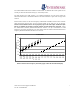
1 System Description Congratulations for buying the smallest, precision orientation tracker on the market! technology offers you several advantages: This Very low latency Wireless range up to 100 feet (30 meters) Smooth, jitter-free tracking Low power consumption The Wireless InertiaCube3 is an inertial 3-DOF (Degree of Freedom) orientation tracking system.
The amber LED on both devices indicates wireless traffic. It should be off at start up then turn on and stay on when the InterSense Library (i.e. isense.dll) is active. The both devices have PCB antennas. For optimal performance, do not enclose either the Wireless InertiaCube3 or InertiaCube3 Receiver in metal containers or place close to large metal surfaces. Because these devices use the same frequency at Bluetooth and 802.
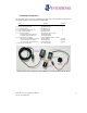
InertiaCube3 Components The following parts list shows all components that ship with a standard Wireless InertiaCube3 (IC3) under InterSense order number ISC-IC30W-PAK0.
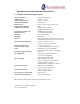
Specifications and Performance Characteristics 1.
2 Wireless InertiaCube3 Support Software Test software and the InterSense Software Development Kit (SDK) delivered with the InertiaCube3 are provided on the InterSense Support CD with the system. Use the auto install tool to extract and install the software on your Windows PC. The core of all InterSense software running on a Windows PC is the isense.dll. When installed with the auto installer Product CD, the isense.dll is automatically place in the WINDOWS or WINNT system directory.
3 Wireless Configuration with deviceTool deviceTool is an application used to test and configure the Wireless InertiaCube3 and the Wireless InertiaCube3 Receiver. To use deviceTool, you must have the Wireless InertiaCube3 Receiver(s) connected to the Windows PC running deviceTool. Also, any of the Wireless InertiaCube3(s) that are being tested or configured, must be powered and within range of the Wireless InertiaCube3 Receiver(s). There are 16 channels available for the InertiaCube3 to use.
DeviceTool will then prompt you to choose an InertiaCube3 if more than one is detected (as shown below). Some information about the InertiaCube3 will then be displayed. Click OK. (If a warning appears to say that no station was found, click OK as well). Wireless InertiaCube3 Supplemental Manual Doc. No.
Then under the Wireless menu item select “ Show Links”(or click on the antenna icon in the tool bar). A new display will show representations of the communication ports with receivers attached to the computer and associated links to InertiaCube3s. Wireless Links shown for Two InertiaCube3 Receivers and one Wireless InertiaCube3 Wireless InertiaCube3 Supplemental Manual Doc. No.
Next, make sure power is applied to all Wireless InertiaCube3s and then se l e c t“ Se a r c hf or St a t i on s ”u n d e rt h eWi r e l e s sme n ut of i n da l lWi r e l e s sI n e r t i a Cu be 3si nt h ea r e a . The dialog box appears warning you to make sure other Wireless InertiaCube3 devices are not being used by others in the area. Select Yes to continue. While searching, the yellow light on the Wireless InertiaCube3 Receiver(s) flashes. Wireless InertiaCube3 Supplemental Manual Doc. No.
Once the search is complete, following window displays all Wireless InertiaCube3 devices found in the area. The display will also summarize the device, port, channel, and InertiaCube ID number. Two Wireless InertiaCube3 Receivers and three Wireless InertiaCube3s Ports with receivers attached are shown as blue boxes. Links associated with a port are shown as boxes to the right of the port and are each connected with line to the port (normally colored green).
Note: The COM port reported by deviceTool can either be a physical or virtual COM port depending on your Wireless InertiaCube3 Receiver configuration. For USB InertiaCube3 Receivers, the USB driver software assigns a virtual COM port to Windows OS for communications. For RS-232 Serial receivers, the physical COM port is used & reported by deviceTool. 3.
The following dialog box appears asking for a wireless channel number. Finally the window below confirms the wireless channel number change (here the channel is changed from 1 to 15). Wireless InertiaCube3 Supplemental Manual Doc. No.
3.3 Attach Wireless InertiaCube3 to Wireless Receiver First, find all available InertiaCube3s on all channels. Under the Wireless menu item select “ Search for Stations” . This causes one of the receivers to sequentially go through all 16 channels searching for available Wireless InertiaCube3s. When deviceTool is done searching, it will display wireless InertiaCube3s that are not associated to a receiver as orange boxes and those already attached to a receiver are displayed as green boxes.
The deviceTool Window below shows that all Wireless InertiaCube3 devices are assigned a channel and linked to a receiver. If you attempt to link a Wireless InertiaCube3 to a non-contiguous of the receiver, the following suggestion will appear. For optimal performance, follow the suggestion above by clicking Yes and reconfigure the system to use contiguous links to the receiver. You can exit the deviceTool program when done.
3.4 Testing the Wireless Link of InertiaCube3 Devices deviceTool is also used to test and verify the wireless communication channels used with the InertiaCube3. To verify which physical InertiaCube3 corresponds to each box in the window, select a Wireless InertiaCube3 box and choose “ Test Link”from the Wireless menu or press the space bar. The yellow LED for the InertiaCube3 will light up.
To verify Wireless InertiaCube3 device information (i.e. version number, port number, channel n umbe r ,e t c …) ,s e l e c te i t h e rt h eWi r e l e s sRe c e i v e ror Wireless InertiaCube3 box in the main deviceTool window then choose “ Get Info”from the Wireless menu. See window below. A dialog box appears with the device information. Wireless InertiaCube3 Receiver Information Window Wireless InertiaCube3 Supplemental Manual Doc. No.
Wireless InertiaCube3 Information Window 4 Wireless InertiaCube3 Power Requirements (Battery) The Wireless InertiaCube3 requires 5.2 to 9 VDC at a drain of 60 mA. Voltages above 9 Volts can cause permanent damage to regulators. Voltages below 5.2 VDC will cause the accuracy of the InertiaCube3 to degrade. The green LED will flash when the detected voltage is at 5.2 VDC, indicating a low power situation and will continue flash until the power is raised above 5.5 VDC. If the detected voltage drops below 4.
The IC3 will produce the same accuracy of results no matter what orientation it is mounted in, but its natural coordinate system is with the base down and cable coming out the back. If it is mounted in another orientation then coordinate transformation will either have to occur in your application or using boresight commands.