INSTALLER’S & OWNER’S MANUAL HVAC INSTALLER: PLEASE LEAVE MANUAL FOR HOMEOWNER P/N 4025700 • Serial No.___________________________ The Ultra-Aire 90H dehumidifier performs multiple functions in a compact enclosure; high-capacity dehumidification, fresh air ventilation, and particulate filtration. Fresh Air Ventilation (optional) Dehumidification Air Filtration The highly efficient UA-90H dehumidifier utilizes refrigeration to cool the incoming air stream below its dew point.
TABLE OF CONTENTS Introduction ..............................................................................1 4.9A Setting the Time .....................................................9 Features & Benefits ..................................................................1 4.9B Ventilation Schedule ...............................................9 Safety Precautions . ..................................................................3 4.9C Automatic or Manual Mode ....................................
SAFETY PRECAUTIONS Read the installation, operation and maintenance instructions carefully before installing and operating this device. Proper adherence to these instructions is essential to obtain maximum benefit from your Ultra-Aire 90H indoor air quality system. READ AND SAVE THESE INSTRUCTIONS • The device is designed to be installed INDOORS IN A SPACE THAT IS PROTECTED FROM RAIN AND FLOODING. • Install the unit with space to access the front panel for maintenance and service.
FOR HVAC INSTALLER ONLY 1. Intended Application for Ultra-Aire 90H n4 .1C Low Voltage Wiring Unit location should be in an area where field wiring the remote controls (low voltage) to the unit will be possible. For the ideal installation, draw air from the central part of the home and return it to isolated areas of the home like the bedrooms, den, utility room, or family room. The ductwork of the existing heating system can be used to supply air to the home. n4 .
FOR HVAC INSTALLER ONLY remote location when the water level in the pump’s reservoir rises to close the float switch. The pump also contains a safety float switch. The white leads from this switch extend from beneath the pump cover. This switch should be installed in series with the field wire that connects the blue (#5) lead from the UA-90H to the the control panel. If the pump fails, this switch opens the compressor control circuit and stops water production before the reservoir overflows.
FOR HVAC INSTALLER ONLY Isolated Areas: Effective dehumidification may require that ducting be branched to isolated, stagnant air flow areas. Use 8" or larger diameter branch ducting to each of two or three areas, use 6" or larger to each of four or more areas. Provisions must be made to provide airflow from supply locations to central return location. Proper air distribution is important to ensure even humidity control and heat distribution throughout the structure. See Figure 1.
FOR HVAC INSTALLER ONLY 4.4E Installation in a Structure with No Existing Forced Air HVAC System Crawlspace Installation: Install a separate return for the UA-90H in a central area of the structure. Optional: Duct the supply of the UA-90H to a 10" x 10" x 10" tee/damper that is 20% open to the crawlspace if desired. Duct the other side of the tee to the air supply of the existing HVAC system with a backdraft damper.
FOR HVAC INSTALLER AND HOMEOWNER To determine how each control operates the UA-90H, it must first be determined which control is being used and whether or not the 90H is ducted for fresh air ventilation. Refer to appropriate section. When the fan/filter switch is in the “ON” position, the motorized damper will open and the fan will run, introducing outside air. The unit may or may not be dehumidifying in the ventilation mode, depending on the humidity control setting. See Section 4.
FOR HVAC INSTALLER AND HOMEOWNER 4.9 Ventilation Timer 4.9B Ventilation Schedule The ventilation timer controls the fan and the motorized fresh air damper. When the ventilation timer is activated, the UA-90H will circulate the indoor air, and bring in fresh air from outside. The ventilation timer should be set for the required ventilation of the residence. The home should be ventilated with fresh air as suggested by applicable codes and standards or as required by the homeowner.
FOR HVAC INSTALLER ONLY 5. DEH 3000 Digital Control Installation Instructions 8. Test connections (see Section 2.6) Control Part No. 4026570 5.1 Specifications Part # (P/N) Model: Electrical: Humidity Range: Humidity Accuracy: Output: Relay Capacity Temp Range/Accuracy Size 4026570 DEH 3000 Digital Control 24 VAC 10 – 95% RH +/- 5% 3 Amps 24 VAC 5 Amps 2% 4.95" wide x 4.19" high 5.
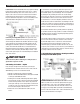
FOR HVAC INSTALLER ONLY Green Yel low Red COM/NO COM/NC ON CLOSED OPEN OFF OPEN CLOSED Common uses (assuming standard thermostat wiring color schemes as noted): 24 VAC DAMPER Blue UA Base Unit White optional Dehumidification Operation Disengage A/C during dehumidification Redirect the yellow thermostat wire to the NC terminal. Wire the yellow wire from the A/C to the COM (B) terminal.
FOR HVAC INSTALLER ONLY DEHUMIDIFIER DEACTIVATES WHEN THE AIR-CONDITIONER IS RUNNING • The common wire on the thermostat transformer (black) needs to be wired with the yellow wire from the dehumidifier. motorized damper in series with these connections, or the white wire must not be connected to the control. Mis-wiring may result in transformer damage. • The Red wire on the thermostat needs to be wired with the Yellow wire from the dehumidifier. 1.
FOR HVAC INSTALLER AND HOMEOWNER 8. Verify additional optional control operations such as fan interlock or lockout. 9. Proceed to operation/setting section. FOR INSTALLER & HOMEOWNER: 5.3 Operation 5.3A Display • When there is power to the control, the control display will show the time, day, humidity, and temperature. • When the control is turned on, the setpoint, fan status, auto/hold mode, and fresh air vent status is displayed. • When a key is pressed the display will light.
FOR HVAC INSTALLER ONLY AND HOMEOWNER Operation The initial dead band setting (the range that the dehumidifier cycles on and off) is 3%. With a setpoint of 50%, the dumidifier turns on when the reading reaches 53%. The dehumidifier continues to remove water from the air until the reading is 47%. The dehumidifier remains off until the reading is 53%. continuously are filtration and air recirculation. “AUTO” – indicates the fan will run when the control calls for dehumidification or ventilation.
FOR HVAC INSTALLER ONLY AND HOMEOWNER The ventilation indicator “O” will be displayed whenever the unit is ventilating. The fan operation indicator “O” will also be lit. There are two programs available for ventilation Monday through Friday. There are also two programs for Saturday and Sunday. No other choice of days is available. There are three damper operation modes, “OPEN – hold,” “CLOSED – hold” and “PROGRAM” (denoted by “ON TIME” – “OFF TIME.” Refer to section 3.8).
FOR HVAC INSTALLER AND HOMEOWNER 2. Press the program enter key to toggle to the “open for” setting. Using the up/down “RH” keys, change the duration that the damper will ventilate fresh air. feature will not need to be used. If temperature cutout is desired, program the setpoint by pressing the “program enter” button. Press RH until “temp cutout” is flashing. Use “RH” up or “RH” down to adjust setpoints. 3. Press the program enter key to toggle to the “closed for” setting.
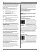
ATTENTION INSTALLER WIRE THE UNIT AND CONTROL PACKAGE AS SHOWN IN THE DIAGRAM BELOW Humidity/Fan Control Panel Humidity Control D.BLU-5 YEL-2 2 1 Blower Switch 3 GRN-6 PNK GRN-6 WHT-1 RED-3 YEL-2 D.BLU-5 Dehumidifier Control Part No. 4024155 Ventilation Timer/ Humidity Control Panel Do not connect these leads directly together or damage to the transformer will result. Optional Damper Humidity Control D.BLU-5 YEL-2 3 2 1 PNK REd-3 GRN-6 WHT-1 RED-3 YEL-2 D.
FOR HVAC INSTALLER AND HOMEOWNER 7. Maintenance 7.1 Standard Air Filter The UA-90H is equipped with a MERV 11 media filter. This filter should be checked every three months. Operating the unit with a dirty filter will reduce dehumidifier capacity and efficiency and may cause the compressor to cycle off and on unnecessarily on the defrost control. DO NOT operate the unit without the standard filter or with a less effective filter than the standard filter.
ULTRA-AIRE 90H WIRING DIAGRAM 8.
FOR HVAC INSTALLER ONLY 9. Optional Parts List: UA-90H Indoor Air Quality System Item Part No.
FOR HVAC INSTALLER ONLY 10. Service Parts List: UA-90H Indoor Air Quality System Item Part No. Description 1 2 3 4 5 6 7 8 4023648 4023681 4022484 4024912 4025561 4020924 4022487 4025544 Compressor, Carlyle (EAA070111A) Compressor Overload (EAA070111A) Compressor Relay, SPST, 24 Vac, 30A Compressor Run Capacitor, 25 MFD Fan Fan Relay, SPDT, 24 Vac, 15A Transformer, 120/24 Vac, 40 VA Condenser, Evaporator, Strainer & Capillary Tube Assembly FOR HOMEOWNER - ROUTINE MAINTENANCE Item Part No.
FOR HVAC INSTALLER ONLY 11. Service 11.2 Troubleshooting No dehumidification, neither fan nor compressor run with fan switch and ventilation timer OFF. 1. Unit unplugged or no power to outlet. 2. Humidity control set too high or defective. 3. Loose connection in internal or control wiring. 4. Defective Compressor relay. 5. Defective control transformer. 6. Optional Condensate Pump Safety Switch open.
FOR HVAC INSTALLER ONLY Unit not providing ventilation. Ventilation timer not operating correctly. 1. If timer is not functioning correctly reset timer and reprogram. 2. Check control wire connections (check connections at fresh air damper also). 3. Defective fresh air damper. 4.Defective fan switch. 11.4 Compressor/Capacitor Replacement This compressor is equipped with a two terminal external overload and a run capacitor, but no start capacitor or relay.
CONDENSATE PUMP INSTALLATION: FOR HVAC INSTALLER ONLY 24 Ultra-Aire 90H Installer’s & Owner’s Manual
CONDENSATE PUMP INSTALLATION: FOR HVAC INSTALLER ONLY 25 Ultra-Aire 90H Installer’s & Owner’s Manual
CONDENSATE PUMP INSTALLATION: FOR HVAC INSTALLER ONLY 26 Ultra-Aire 90H Installer’s & Owner’s Manual
CONDENSATE PUMP INSTALLATION: FOR HVAC INSTALLER ONLY 27 Ultra-Aire 90H Installer’s & Owner’s Manual
CONDENSATE PUMP INSTALLATION: FOR HVAC INSTALLER ONLY 28 Ultra-Aire 90H Installer’s & Owner’s Manual
CONDENSATE PUMP INSTALLATION: FOR HVAC INSTALLER ONLY 29 Ultra-Aire 90H Installer’s & Owner’s Manual
ULTRA-AIRE 90H Dehumidifier Limited Warranty WARRANTOR: LIMITATIONS AND EXCLUSIONS: This warranty does not cover any defect, malfunction, etc. resulting from misuse, abuse, lack of normal care, corrosion, freezing, tampering, modification, unauthorized or improper repair or installation, accident, acts of nature or any other cause beyond Therma-Stor LLC’s reasonable control. This excludes charges incurred installing and removing UltraAire 90H for repair.
PO Box 8680 • Madison, WI 53708 Phone: 608-222-5301 • Fax: 608-222-1447 Web: www.thermastor.com • Email: sales@thermastor.com Information in this document is subject to change without notice. No part of this document may be reproduced or transmitted in any form or by any means, electronic or mechanical, for any purpose, without the express written permission of Therma-Stor LLC. © 2006 Therma-Stor LLC. All rights reserved.