
owner's Manual dehumidifier 90H


1. Intended Application for Ultra-Aire 90H
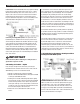
For the ideal installation, draw air from the central part of the home
and return it to isolated areas of the home like the bedrooms, den,
utility room, or family room. The ductwork of the existing heating
system can be used to supply air to the home.
2. Registrations
The UA-90H conforms to UL STD 474 and CSA Standard C22.2
No.92.
3. Specifications
Model: Ultra-Aire 90H
Electrical: 110-120 VAC, 6.3 Amps, 60 Hz, grounded
Capacity: 90 pints/day @ 80°F, 60% RH
Operating Temp.: 56°F min., 100°F max.
Air Flow: 200 CFM without external ducting
Refrigerant Charge: 1 lb., 12 oz. R22
Duct Connections: Round 10" inlet, 10" outlet,
6" ventilation inlet Filter Size: Pleated cloth: 14" X 14" X 1"
Unit Size (w/o duct collars): 34
1
/
2
"L x 15
3
/
4
"W x 20
7
/
8
"H Unit
Weight: 92 lbs Shipping Weight: 99 lbs
4. Installation
4.1 Installation Checklist
IMPORTANT
Prior to installation of the UA-90H, the following checklist should
be reviewed. The UA-90H can be installed in a variety of locations
to meet the owner’s needs, and integrate with existing forced
air systems or existing ductwork if desired. The location choice
is contingent on a variety of requirements not limited to: ease
of service, controls access, drainage, filtration, power, fresh-air
ventilation, water damage prevention, and current regulatory codes
(ASHRAE, fire, etc). Please address all of these issues before you
select the device’s location.
n 4.1A Power Accessibility
Unit should be located in an area where the cord’s length (10’)
should easily reach a 115 VAC electrical outlet with a minimum of
a 15 A circuit capacity.
n 4.1B Space
Location should have enough clearance to handle the unit’s overall
dimensions as well as the necessary return/supply ductwork to the
unit.
n 4.1C Low Voltage Wiring
Unit location should be in an area where field wiring the remote
controls (low voltage) to the unit will be possible.
n 4.1D Back-Draft Damper
It is recommended that a back draft damper be used in the
discharge duct of the UA-90H, especially when connecting to the
supply ducting system. The backdraft damper prevents supply air
from counter flowing through the UA-90H when it is not operating.
The unit location should be chosen to allow installation of this
accessory if requested by the end user.
n 4.1E Support Structure and Suspension
Place the UA-90H on supports to raise the base of the unit. Do not
place the UA-90H directly on structural building members without
vibration absorbers or unwanted noise may result.
The UA-90H may be suspended with steel hanger straps (plumbers
tape) or a suitable alternative from structural members, as long
as the suspending assembly supports the UA-90H’s base in its
entirety. Do not hang the UA-90H from the cabinet. Remember to
place a drain pan under the unit if it is suspended above a finished
area or above an area where water leakage could cause damage.
4.2 Electrical Requirements
WARNING
WARNING: DO NOT ALLOW THE YELLOW LEAD FROM
THE ULTRA-AIRE TO CONTACT THE RED LEAD FROM THE
ULTRA-AIRE OR DAMAGE TO THE TRANSFORMER WILL
RESULT.
The UA-90H plugs into a common grounded 115VAC outlet. The
device draws 6.3 Amps under normal operating conditions. If used
in an area which may become wet, a ground fault interrupter (GFI)
protected circuit is recommended. Please, consult local electrical
codes for any further information.
Therma-Stor LLC offers a family of control devices for use with the
UA-90H. The controls are to be located remotely from the unit and
located in the space to be conditioned. The controls are low voltage
(24 volt) and should be connected to the UA-90H with low voltage
wire (thermostat or other appropriate).
FOR HVAC INSTALLER ONLY
4
Ultra-Aire 90H Installer’s & Owner’s Manual
5
Ultra-Aire 90H Installer’s & Owner’s Manual