INSTALLER’S & OWNER’S MANUAL Ultra-Aire 150H Whole House Ventilating Dehumidifier UA-150H • Part No. 4024371 • Serial No.________________________________ Dehumidification Fresh Air Ventilation The highly efficient Ultra-Aire 150H dehumidifier utilizes refrigeration to cool the incoming air stream below its dew point. This cooled and drier air is used to pre-cool the incoming air stream resulting in a significant increase in overall efficiency.
TABLE OF CONTENTS Table of Contents Safety Precautions........................................................................ 3 5.3H Damper Operation and Setting ................................ 13 1. Intended Application................................................................. 4 5.3I Intermittent/Programmed Ventilation ........................ 14 2. Specifications .......................................................................... 4 5.3J Programming Notes . ............................
SAFETY PRECAUTIONS 1. Safety Precautions Read the installation, operation and maintenance instructions carefully before installing and operating this device. Proper adherence to these instructions is essential to obtain maximum benefit from your UA-150H indoor air quality system. READ AND SAVE THESE INSTRUCTIONS • The device is designed to be installed INDOORS IN A SPACE THAT IS PROTECTED FROM RAIN AND FLOODING. • Install the unit with space to access the front panel for maintenance and service.
FOR HVAC INSTALLER ONLY 1. Intended Application for Ultra-Aire 150H Place the UA-150H on supports that raise the base of the unit above the top of the flanges on the drain pan beneath it. Raising the UA-150H will help the unit drain with gravity flow. Do not place the UA-150H directly on structural building members without vibration absorbers or unwanted noise may result.
FOR HVAC INSTALLER ONLY 3.4B Ducting for Dehumidification careful not to cross the wires when connecting the UA-150H and the remote control panel or damage to the transformer may result. For the ideal installation, draw air from the central part of the home and return it to the isolated areas of the home like the bedrooms, den, utility room, or family room. The ductwork of the existing heating system can be used to supply air to the home.
FOR HVAC INSTALLER ONLY 3.4C Ducting for Fresh Air 3.4D Installation in a Basement or Crawlspace with an Existing Forced Air HVAC System Fresh air can be brought into the structure by connecting a insulated duct from outside to the 6” UA-150H inlet and by turning on the fan switch or activating the humidity control (on units with the humidity control panel). Activate the ventilation timer on units with the ventilating & humidity control panel to bring in fresh air. Refer to section 4.
FOR HVAC INSTALLER ONLY 3.4E Installation in an Attic with an Existing Forced Air HVAC System 3.5 Quiet Installation The compressor is attached to the cabinet with two cable ties to secure it during shipment. This rigid attachment is not necessary once the unit is installed and may cause noise from compressor vibration. After installation, cut the cable ties to free the compressor from the cabinet.
FOR HVAC INSTALLER ONLY 4.4 Fan/Filter Switch panel has a cover that must remain open to the air within the living space for accurate humidity sensing. Position the fan switch on when the home is occupied. The impeller fan blends fresh air with the inside air. It also filters and circulates the blended air throughout the home. Turning ON the fan/filter switch will cause the the UA-150H impeller fan to run continuously, whether the UA-150H is dehumidifying or not.
FOR HVAC INSTALLER ONLY Automatic or Manual Mode: The slide switch in the upper left of the timer is used to choose between automatic and manual operation of the timer relay. When the slide switch in the upper left of the timer is set to AUTO mode, the UA-150H will ventilate when the scheduled programs call for ventilation. When the slide switch in the upper left of the timer is set to manual (set to hand symbol on the right), the operation of the timer is controlled by the I/O button only.
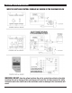
ATTENTION INSTALLER WIRE THE UNIT AND CONTROL PACKAGE AS SHOWN IN THE DIAGRAM BELOW WARNING: DO NOT allow the yellow lead from the unit to contact the red lead or the white lead from the unit or damage to the transformers will result. Do not direct connect the white lead on the unit to the violet lead on the ventilation control or damage to the transformer will result.
FOR HVAC INSTALLER ONLY 5. (DEH 2000) DIGITAL CONTROL Installation Instructions 6. Align the back panel against these screws, pushing it forward, allowing it to slide downward to lock into position. 7. Make the electrical connections to the terminals on theback panel as shown in the wiring diagram. 8. Seal the hole around the wires to prevent air movement. 9. Reconnect the quick connector onto the back panel. 10. Reassemble the front to the back panel. Connect at the top first, then at the bottom.
FOR HVAC INSTALLER AND HOMEOWNER • The word “CLOCK” appears at the top of the display during the clock display, along with the day and time. • The word “HUMIDITY” appears during the humidity display, with the current Set point on the left, and the ambient RH on the right. • The word “TEMP” appears as the unit displays the current temperature. • The fan status display is indicated by a capitol “F”. “OF” indicates fan off status, “on” indicates fan on status.
FOR HVAC INSTALLER ONLY AND HOMEOWNER 5.3E Setting Relative Humidity Set point “on” mode, the fan will run continuously. This does not effect the dehumidification functions of the system. The system may or may not be ventilating or dehumidifying while the fan is running. Common reasons for operating the fan continuously are continuous filtration and air recirculation. With the fan in the “off” or “program” mode, the fan will operate only when needed by other functions of the system.
FOR HVAC INSTALLER ONLY AND HOMEOWNER 6.3I Intermittent or Programmed Ventilation With the damper in program mode (denoted by “Pr” when setting the damper operation) the system will operate the ventilation function according to the current ventilation program. 9. Pressing the “PROG” button again to move onto “program 2/stop” and begin the process again if setting the other programs. Follow the same procedure for each program. 10.
FOR HVAC INSTALLER ONLY 6. Maintenance 7. Service The UA-150H is equipped with a pleated cloth air filter. This filter should be checked every three months. Operating the unit with a dirty filter will reduce dehumidifier capacity and efficiency and may cause the compressor to cycle off and on unnecessarily on the defrost control. A warranty certificate has been enclosed with this unit; read it before any repair is initiated.
FOR HVAC INSTALLER ONLY 7.3 Troubleshooting Evaporator coil frosted continuously, low dehumidifying capacity. 1. Defrost thermostat loose or defective (Sec. 5.8). 2. Low refrigerant charge 3. Dirty air filter(s) or airflow restricted. 4. Excessively restrictive ducting connected to unit. No dehumidification, neither impeller fan nor compressor run with fan switch and ventilation timer OFF. 1. Unit unplugged or no power to outlet. 2. Humidity control set too high or defective (Sec. 3.3 & 5.7A) 3.
FOR HVAC INSTALLER ONLY 7.4 Refrigerant Charging 5. Compressor terminals C and R: No continuity indicates an open run winding. The compressor must be replaced. Normal run winding resistance is .5 to 2 ohms. 6. Compressor terminal C and overload terminal 1: No continuity indicates a defective overload lead. 7. Overload terminals 1 and 3: If there is no continuity, the overload may be tripped. Wait 10 minutes and try again. If there is still no continuity, it is defective and must be replaced. 8.
FOR HVAC INSTALLER ONLY If sludge is evident in the discharge line, it will likely be found in the suction line. This indicates the compressor burned out will running. Sludge and acid have been pumped throughout the system. Several changes of the liquid and suction filter/driers will probably be necessary to cleanse the system. (see back of control panel cover). ). If it still does not run, remove the stop screw from the panel and turn the knob farther.
FOR HVAC INSTALLER ONLY 7.11 Condensate Pump Kit If the electric ventilation damper fails to operate: 1. Check that the wiring is correct and that voltage is present at the damper motor. 2. Check for any obstruction inside the damper. If the electric ventilation damper fails to operate after performing these checks, it must be replaced. An optional condensate pump kit is available from the factory for use with the UA-150H.
FOR HVAC INSTALLER ONLY Pictorial Electrical Diagrams of UA-150H 20 Ultra-Aire 150H Installer’s & Owner’s Manual
FOR HVAC INSTALLER ONLY Wiring Diagrams 21 Ultra-Aire 150H Installer’s & Owner’s Manual
SERVICE PARTS LIST: UA-150H ITEM 1 2 3 PART NO. 4024369 4017777 4023645 4 5 6 7 8 9 10 11 12 13 14 15 16 17 18 19 20 21 22 23 4022595 4022484 4022740 4022563 4021470 4021648 4022557 4024270 4020924 4024360 4025087 4021626 4024368 4023928 4022219 4021332 4022487 4024359 40218181 4024365 4024361 QTY. DESCRIPTION 1 Air Filter, Pleated Cloth 2 Capillary Tube, .059" X .124" X 32.
OPTIONAL PARTS LIST: UA-150H ITEM 25 26 27 28 29 30 31 32 33 34 35 36 37 38 39 PART NO. 4024370 4024375 4022220 4024155 4024125 4023660 4023672 4024153 4021495 4024150 4024122 4025560 4022486 4024377 4024431 QTY.
VIBRATION ISOLATION KIT: UA-150H INSTRUCTIONS FOR ASSEMBLING THE VIBRATION ISOLATORS TO THE 150H 1. Lift one end of the UA-150H at least 12” off the floor. 2. Slide (2) of the nuts over each screw. 3. Attach the screws (with nuts) to the holes located in the bottom corners of the UA-150H. 4. Slide the grommet over the screw and nuts assembly. 5. Repeat for the other end of the UA-150H.
EXTERNAL INSULATION KIT: UA-150H INSTRUCTIONS FOR APPLYING THE INSULATION TO THE UA-150H Install the insulation kit as shown in the illustration below. After installing the insulation, cut out the holes for the supply and return connections and cut the seam around the removable front cover so it can be removed easily. If more insulation is needed two or more insulation kits may be applied to a single UA-150H. The UA-150H must be clean, dry and at room temperature to apply the insulation kit.
ATTENTION INSTALLER 26 Ultra-Aire 150H Installer’s & Owner’s Manual
ULTRA-AIRE 150H Dehumidifier Limited Warranty WARRANTOR: from misuse, abuse, lack of normal care, corrosion, freezing, tampering, modification, unauthorized or improper repair or installation, accident, acts of nature or any other cause beyond Therma-Stor LLC's reasonable control.
PO Box 8680 • Madison, WI 53708 Phone: 608-222-5301 • Fax: 608-222-1447 Web: www.thermastor.com • Email: sales@thermastor.com Information in this document is subject to change without notice. No part of this document may be reproduced or transmitted in any form or by any means, electronic or mechanical, for any purpose, without the express written permission of Therma-Stor LLC. © 2006 Therma-Stor LLC. All rights reserved.