PATIO DOOR SYSTEMS ® Therma-Tru Hinged Patio Door System Single Panel Unit Assembly Read all instructions before starting. The applicable standards for these products are governed by the International Residential Code. Copies of performance ratings and testing are available on our website www.thermatru.com and our product manual.
Part identification Not all parts shown will be included in package. Parts will vary for type of unit purchased.
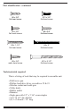
Part identification - continued #6 x 3/4” flat head screw #10 x 3/4” flat head screw #8 x 5/8” flat head screws #8 x 3/4” flat head screw #8 x 1-1/4” flat head screw #8 x 2” flat head screw #8 x 3/4” wafer head screw #10 x 2-1/2” flat head screw Tools/materials required This is a listing of tools that may be required to assemble unit.
NOTE: A large work area is needed to assemble the frame kit. Cover area with cardboard from one or more door panel cartons to protect frame parts and floor. If available a carpeted table can be used to avoid marring prefinished surfaces. 1 REMOVE COMPONENTS FROM PACKAGING NOTE: Product that is purchased with the multi-point lock system will have additional instructions in the handle hardware box. Installation instructions will be included in the site package.
2 ATTACH HINGES TO DOOR - continued Adjustable Hinge Option “H” marked hinge shown Attach hinge to door Marking Locate the “H” and “V” markings on hinges. The two “H” hinges go in top and bottom locations with the “V” hinge in the center. For 8’, the “V” hinge is located second from top of door. Insert thick side of hinge into pocket in door and fasten with #8 x 1-1/4” flat head screws. NOTE: Inswing hinges are reversible by removal of hinge pin.
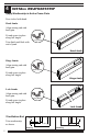
4 INSTALL WEATHERSTRIP Apply Weatherstrip to Active Frame Parts Press in kerf with hand. Head Jambs Align starting end with head gain. Fit and secure in place along full length. Long Reach Trim finish end flush with end of jamb. Head Jamb Hinge Jambs Align starting end with head gain. Short Reach Fit and secure in place along full length. Hinge Jamb Lock Jambs Align starting end with head gain. Long Reach Fit and secure in place along full length.
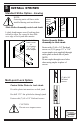
5 INSTALL STRIKES Standard Strike Option - Inswing NOTE: Outswing units will have strike installed during unit installation. Adjustable security backing plate Slide Strike Assembly onto Lock Jamb Lightly bend tongue area of backing plate inward to allow for a snug fit then slide over edge of lock jamb into mortise.
6 ATTACH HINGES TO JAMB NOTE: These are instructions for installation of standard hinges. Proceed to step 7, FRAME ASSEMBLY, if using adjustable hinges. Standard Hinge Option Fasten Hinges to Hinge Jamb Leave Holes Vacant Place hinges into hinge mortise. Pre-drill 1/8” dia. pilot holes through jamb. Fasten top hinge with (2) #10 x 3/4” flat head screws in hole locations shown. Fasten middle and bottom hinges each with (3) #10 x 3/4” flat head screws leaving top hole vacant.
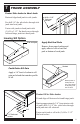
7 FRAME ASSEMBLY Fasten Side Jambs to Head Jamb Butt and align head jamb to side jambs. Pre-drill 1/8” dia. pilot holes through side jamb into head jamb. #10 x 2 1/2” flat head screws Fasten side jambs to head jamb with (3) #10 x 2 1/2” flat head screws through lock and hinge jamb into head jamb. Inswing Sill Option End seal pad Apply End Seal Pads Remove from paper backing and apply adhesive side of end seal pads at bottom of each jamb.
7 FRAME ASSEMBLY - continued Outswing Sill Option Partially Set Sill Screws in Jambs Drive (1) #8 x 2” flat head screw through holes in both side jambs until tips barely protrude through jamb face. Flat head screw #8 x 2” Caulk Entire Sill Gain Apply a 1/4” bead of sealant to sill gain and a bead that matches upper profile of sill. Sealant Fasten Sill to Jamb Use screw points and index sill in place. Drive screws using bit sized properly for screw head. Pre-drill (2) 3/32” dia.
8 FLANGE INSTALLATION Inswing Outswing NOTE: Inswing application shown. Align and Install Side Flanges Align edge of side flange with bottom of side jambs. Align e Sid n Fla ge Firmly press into kerf in jamb using a rubber mallet if necessary. Flange will be set back approximately 1/2” from top edge of jamb. Install Top Flange Center top flange into head jamb kerf and press into place using a rubber mallet if necessary.
9 DOOR INSTALLATION Standard Hinge Option Make 2 “Insert Skids” 38" 2" Make from 2 x 6 boards. 3" NOTE: It is recommended to cover skids with cardboard or other material to protect surface of door. For 6-9/16" jambs For 4-9/16" jambs 12-1/8" 3/8" 2x6 Place Door into Frame Hinge Lay frame on flat surface with hinges on jamb pointed up as shown. Skid (2) Door Frame Door Skid Hinge 4-9/16" Jambs Jamb Door Skid Hinge 6-9/16" Jambs 11 Jamb Slide door down on top of skids.
9 DOOR INSTALLATION - continued Engage Hinge Knuckles Tap with hammer or rubber mallet as required to line up hinge knuckles and engage. Install Hinge Pins Hinge Pin Door Tap in pins. Be certain to insert pins so heads are on top edges of hinges. Door Frame Adjustable Hinge Option Fasten door panel to frame Prop up hinge side of door panel until hinges can align into mortises on hinge jamb. Fasten door panel to frame with #8 x 3/4” flat head screws, (2) in top hinge and (3) in middle and bottom hinge.
10 ATTACH TRANSPORT CLIP Standard Lock Option Transport Clip Attach Transport Clip to Door Insert tab into latch bore. Exterior side Position reference lip at edge of stile against exterior side of door. Fasten with (2) #6 x 3/4” flat head screws. #6 x 3/4" flat head screws Transport Clip #6 x 3/4” Attach Transport Clip to Frame Close door into frame ensuring margins are even at head jamb. #6 x 3/4" flat head screws Fasten transport clip to frame with (2) #6 X 3/4” flat head screws.
10 ATTACH TRANSPORT CLIP - continued Attach Transport Clip to Door Place flattened transport clip on top of door approximately 1 to 2 inches from lock side edge. #6 x 3/4" flat head screws Fasten with (2) #6 x 3/4” flat head screws. Attach Transport Clip to Frame Close door into frame ensuring margins are even at head jamb. #6 x 3/4" flat head screws 11 Fasten transport clip to frame with (2) #6 x 3/4” flat head screws. UNIT READY FOR INSTALLATION Unit can now be transferred for installation.
PATIO DOOR SYSTEMS 1687 Woodlands Dr. Maumee, OH 43537 1-800-THERMATRU (843-7628) www.thermatru.com © 2004 Therma-Tru Corp. Therma-Tru Doors is an operating company of Fortune Brands, Inc.