I nf r ar edCabi netHeat er MODEL :RC9200I T CAUT I ON-F ORYOURSAF ET Y doorUseOnl y WARNI NG:ForOut mpr operi nst al l at i on,adj ust ment ,al t er at i on,ser vi ceormai nt enance WARNI NG:I cancausepr oper t ydamage,i nj ur yordeat h.Readt hei nst al l at i on,oper at i ngandmai nt anancei nst r uct i onst hor oughl ybef or ei nst al l i ngorser vi ci ngt hi sequi pment . WARNI NG Donotst or eorusegasol i neorot herf l ammabl evapor sandl i qui di nvi ci ni t yoft hi sorany ot herappl i ance.
TABLE OF CONTENTS About Us……………………….….….…1 Product Specifications…………………1 Important Safety Information………….2 Product Features.................................3 Preparing for Installation......................4 Installation............................................4 Air for Combustion and Ventilation......7 Unit Operation…………………….…....8 Care and Maintenance…....................10 Troubleshooting…………....................11 Illustrated Parts...................................15 Parts List....................
IMPORTANT SAFETY INFORMATION IMPORTANT: Read this owner’s manual carefully and completely before trying to assemble, operate, or service this heater. Improper use of this heater can cause serious injury or death from burns, fire, explosion, electrical shock, and carbon monoxide poisoning. Only a qualified installer, service agent, or local gas supplier may install and service this product.
WARNING: Do not use a blower insert, heat exchanger insert or other accessory not approved for use with this heater. WARNING: Failure to position the parts in accordance with these diagrams or failure use only parts specifically approved with this heater may result in property damage or personal injury. This heater needs fresh air ventilation to run properly. This heater has an Oxygen Depletion Sensing (ODS) safety shutoff system. The ODS shuts down the heater if not enough fresh air is available.
PREPARING FOR INSTALLATION Before beginning assembly or operation of the product, make sure all parts are present. Compare parts with package contents list and diagram below. If any part is missing or damaged, do not attempt to assemble, install or operate the product. Contact customer service for replacement parts. Control knob Igniter button Protective front cover Figure 1 – gas heater cabinet UNPACKING 1. Remove heater from carton. 2. Remove all protective packaging applied to heater for shipping 3.
INSTALLATION WARNING: A qualified service person must install heater. Follow all local codes. Check Gas Type Be sure your gas supply is right for your heater. Otherwise, call dealer where you bought the heater for proper type heater. Connect Hose & Regulator to Cylinder 1) You must provide propane gas and propane cylinder. Use a standard 20 lb. propane cylinder. 2) Use this heater only with a propane vapor withdrawal supply system.
10) The propane cylinder must be constructed and marked in accordance with the specifications for LP gas cylinders of the U.S. Department of Transportation (DOT). 11) Never connect an unregulated propane cylinder to the heater. 12) Screw regulator onto gas hose. Dot not cross-thread. 13) Tighten securely. 14) Attach regulator to cylinder. 15) Complete attachment. 16) Install the cylinder and latch closed. 17) Close the rear cover.
CHECKING GAS CONNECTIONS WARNING: Test all gas piping and connections for leaks after installing or servicing. Correct all leaks at once. WARNING: Never use an open flame to check for a leak. Apply a mixture of liquid soap and water to all joints. If bubbles form, there is a leak. Correct all leaks at once. Pressure Testing Heater Gas Connections 1) Open gas supply tank valve. 2) Make sure control knob of heater is in the OFF position. 3) Check all joints from equipment shutoff valve to control valve.
OPERATION FOR YOUR SAFETY READ BEFORE LIGHTING WARNING: If you do not follow these instructions exactly, a fire or explosion may result causing property damage, personal injury or loss of life. Before Turning Gas Supply ON: 1) Your heater was designed and approved for outdoor use only. Do NOT use it inside a building, garage, or any other enclosed area. 2) Make sure surrounding areas are free of combustible materials, gasoline, and other flammable vapors or liquids.
Lighting 1) STOP! Read the safety information on the inside of the heater. User MUST follow these lighting procedures or the heater will NOT operate properly. 2) Make sure equipment shutoff valve is fully open. 3) Turn control knob clockwise to the OFF position. 4) Wait five (5) minutes to clear out any gas. Then smell for gas, including near the floor. If you smell gas, STOP! Do not try to light any appliance. Do not touch electrical switch or use any phone in the building.
CARE AND MAINTENANCE WARNING: Turn off heater and let cool before servicing. Any grills removed for servicing MUST be replaced prior to use. CAUTION: You must keep control areas, burner, and circulating air passageways of heater clean. Inspect these areas of heater before each use. Have heater inspected yearly by a qualified service technician. Heater may need more frequent cleaning due to dirt and other debris normally found outdoors.
CLEANING THE CABINET Air Passageways Use a vacuum cleaner or pressurized air to clean. Exterior Use a soft cloth dampened with a mild soap and water mixture. Wipe the cabinet to remove dust. If you need replacement parts you must go to an authorized dealer for professional service! Every part of the heater shall be secure against displacement and shall be constructed to maintain a fixed relationship between essential parts under normal and reasonable conditions of handling and usage.
No. PROBLEM 1 -When igniter button is pressed in there is no spark at ODS/pilot. 2 -When igniter button is pressed in there is a spark at ODS/pilot but no ignition. POSSIBLE CAUSE -- Igniter electrode is positioned wrong or broken. -- Igniter electrode is not connected to igniter cable. -- Igniter cable is pinched or wet. -- Broken igniter cable. -- Bad piezo igniter. -- Gas supply is turned off or equipment shutoff valve is closed. -- Control knob not fully pressed in while pressing igniter button.
7 8 9 -Yellow flame during burner combustion. -Slight smoke or odor during initial operation. -Heater produces a whistling noise when burner is lit. -- Not enough air. -- Gas regulator is defective. -- Inlet gas pressure is too low. -- Residues from manufacturing processes. -- Turning control knob to HI position when burner is cold. -- Air in gas line. -- Air passageways on heater are blocked. -- Dirty or partially clogged burner orifice.
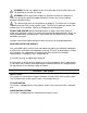
ILLUSTRATED PART Model: RC9200IT 14
PARTS LIST Model: RC9200IT Code 1 2 3 4 5 6 7 8 9 10 11 12 13 14 15 16 17 18 19 20 21 22 23 24 25 26 27 28 Description Main front protective screen Fastener 1 Scatter panel Igniting electrode Burner assembly Burner board Top cover Plastic seat Igniter Igniter assembly Knob Gas pipe nut Plastic seat Gas safety valve Rear back board Fastener Rear cover board Rear insulation board Front insulation board Tip over safety switch Universal wheel-1 Supporting bracket ODS bracket ODS/ODS Radiant panel assembly Sup
Questions about installation and initial operation should be directed to your installer. For all other concerns and questions, please reach out to our customer service team at 1-877-670-8428, by email at service@thermablaster.com, or visit www.thermablaster.com Annual Service Schedule Service Performed Service Date Please register your product online at www.thermablaster.