
Installation Instructions

Page. 22
Setting the STAR
®
burner
valve screws
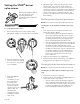
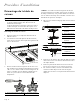
To set the burner valve screws
1. Remove the knob from the valve stem by slowly
pulling knob straight out, away from the control panel.
4. Adjust the valve screw by turning the valve screw
about an 1/8
th
turn. Turn the screw clockwise to
reduce simmer flame size. Turn the screw counter-
clockwise to make the simmer flame larger. Adjust the
valve screw as little as required to reach satisfactory
simmer results. Due to normal fluctuations in gas
pressure, over-adjustment of valve screw may affect
flame stability.
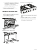
Checking the broil burner(s) performance
NOTE: The oven door(s) must be installed and closed.
Checking the gas broil ignition and flame (gas range
only)
1. Turn on the main oven mode knob and the oven
temperature knob to BROIL.
• The hot-surface igniter will attempt to light the
broiler after approximately 45 to 90 seconds, as
the safety valve coil heats to open. Once the air
has been purged from the gas supply line, the
broiler should light within four (4) seconds.
• Observe the broil flame performance through the
oven door window. The ceramic tiles of the burner
should glow red hot (infrared) after several
minutes of operation. If after several minutes with
the burner lit, the broiler only has a small amount
of red glow (and burns mostly with blue flame
floating on the burner surface), check that the
broiler orifice is aligned to the center of the
burner tube inlet.
2. Repeat for the auxiliary oven, if applicable.
3. If the broil burner burns satisfactorily, reassemble the
backguard onto the appliance (see page 15).
Checking the bake burner(s) performance
NOTE: The oven door(s) must be installed and closed.
Checking the gas bake ignition and flame (gas range
only)
1. Install the front panel (see page 17).
2. Turn the main oven mode knob to BAKE and the oven
temperature knob to any setting.
• The hot-surface igniter will attempt to light the
burner tube after approximately 45 to 90 seconds,
as the safety valve coil heats to open. Once the air
has been purged from the gas supply line, the
burner should light within four (4) seconds.
A flat-head screwdriver with an
1/8" [3.0 mm] wide, .020"
[0.50 mm] thickness tip
(included) is used to adjust the
valve screws.
2. Remove the bezel-mounting
screw located to the right of
the valve stem, using a T-20
torx screwdriver.
3. Insert included 1/8''
flat-blade
screwdriver into the
hole of the bezel
mounting screw.
Access to the valve
screws through the
clearance hole in the
spark module. You
should feel the
engagement of the
screwdriver and the
valve screw.