
Installation instructions

Installation Instructions English 15
Hook Up
The gas supply connections shall be made by a competent
technician and in accordance with local codes or
ordinances. In the absence of local codes, the installation
must conform to the National Fuel Gas Code ANSI Z223.1/
NFPA54- current issue.
1. A manual gas shut-off valve must be installed external
to the appliance, in a location accessible from the front,
for the purpose of shutting off the gas supply. The
supply line must not interfere with the back of the unit.
Make sure the gas supply is turned off at the manual
shut-off valve before connecting the appliance.
• The range is supplied with its own pressure
regulator that has been permanently mounted
within the range body.
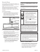
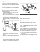
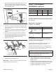
2. Use a ¾'' (19 mm) flex line to connect between the gas
supply and the appliance gas inlet. The gas supply line
connection is located at the lower right portion of all
range models (see Figure 9). The appliance gas inlet
connection is ½'' (12.7 mm) NPT.
• Use caution to avoid crimping the ¾'' (19 mm) flex
line when making bends. Suggested length of flex
line is 48" (1219 mm); however, please check local
codes for your area's requirements before
installation.
3. Use pipe sealing compound or Teflon
®
tape on the
pipe threads. DO NOT apply sealing compound or tape
to flare fittings. Take care not to apply excessive
pressure when tightening the fittings.
4. Leak testing of the appliance shall be in accordance
with the following instructions.
• Turn on gas and check supply line connections for
leaks using a soap and water solution.
• Bubbles forming indicate a gas leak. Repair all
leaks immediately after finding them.
CAUTION
When connecting unit to propane gas, make certain the
propane gas tank is equipped with its own high pressure
regulator in addition to the pressure regulator supplied
with the appliance. The pressure of the gas supplied to
the appliance regulator must not exceed 14" water
column (34.9 mb).
NATURAL GAS REQUIREMENTS
Inlet Connection: 1/2” NPT internal
(Minimum 3/4” dia. flex line)
Supply Pressure: 6" min. to 14" max. water column
(14.9 to 34.9 mb)
Manifold Pressure: 5" water column (12.5 mb)
PROPANE GAS REQUIREMENTS
Inlet Connection: 1/2” NPT internal
(Minimum 3/4” dia. flex line)
Supply Pressure: 11"min. to 14"max. water column
(27.4 mb to 34.9 mb)
Manifold Pressure: 10" water column (24.9 mb)
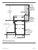
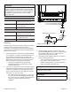
Figure 9: Gas Supply Connection
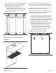
WARNING
Gas line must not come in contact with any components
inside back cover of range.
WARNING
Do not use a flame of any kind to check for gas
leaks.
Adapter
¾" (19 mm) external threads
½" (12.7 mm) internal threads
{
or
Manual gas shut-off valve
or
Adapter
Adapter
Adapter
¾" (19 mm)
Flex line
¾" (19 mm)
Flex line
¾" (19 mm)
Flex line
Manual gas shut-off valve