
Installation instructions


Installation Instructions English 17
4-Wire Connection
A unit must be connected to the power supply with a 3-
POLE, 4-CONDUCTOR cord kit rated 125/250 VOLTS, 50
AMPERES DEDICATED CIRCUIT, and marked for use
with ranges.
The cord kit must be attached to the range terminal block
with a strain relief (not provided) which will fit a 1"
(25.4 mm) diameter hole. If not already equipped, the cord
must also have 1/4'' (6 mm) faston closed-loop lugs
attached to the free ends of the individual conductors,
preferably soldered in place.
1. Locate the terminal block on the rear of the unit and
remove cover (see Figure 10).
2. Remove upper nuts only from the terminal block studs.
Do not remove lower nuts which secure range internal
wiring leads.
3. Mount strain relief (not provided with range) into the 1"
(25.4 mm) diameter hole in the back panel located
below the terminal block. Route wires up through strain
relief.
4. Secure the neutral, grounded wire of the supply circuit,
to the center stud of the terminal block with nut (see
Figure 11).
5. Secure the L1 (red) and L2 (black) power leads to the
outside terminal studs (brass colored) with nuts.
6. Remove green ground screw located beneath the
terminal block. Discard white wire.
7. Secure the bare copper ground lead to the range
chassis using the ground screw previously used for the
white wire. Be sure that neutral and ground terminals
do not touch.
8. Tighten all connections securely.
9. Reinstall the terminal block cover.
INSTALLER — show the owner the location of the circuit
breaker. Mark it for easy reference.
3-Wire Lead Connection
Where local codes and ordinances permit grounding
through neutral, and conversion of supply to 4 wire is
impractical, unit may be connected to the power supply
with a 3-POLE, 3-CONDUCTOR cord kit rated 125/250
VOLTS, 50 AMPERES DEDICATED CIRCUIT, and marked
for use with ranges.
The cord kit must be attached to the range back panel with
a strain relief which will fit a 1" (25.4 mm) diameter hole. If
not already equipped, the cord must also have 1/4'' (6 mm)
faston closed-loop lugs attached to the free ends of the
individual conductors, preferably soldered in place.
1. Locate the terminal block on the rear of the unit and
remove cover.
2. Remove upper nuts only from the terminal block studs.
Do not remove nuts which secure range internal wiring
leads.
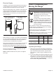
Figure 10: Strain Relief Location
Strain Relief
Strain Relief
Strain Relief
Terminal Block
Terminal Block
Terminal Block
Figure 11: 4-Wire Connection
Red/L1
Wire
Black/L2
Wire
White/
Neutral Wire
Green/
Ground Wire