
Installation instructions

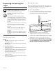
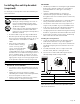

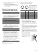
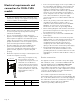
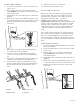
Table Of Contents

Page. 15
Gas requirements and hookup
9 CAUTION
The appliance must be isolated from the gas supply
piping system by closing its individual manual shut-off
valve during any pressure testing of the gas supply
piping system at test pressures equal to or less than 1/
2 psig (3.5kPa.).
9 WARNING
DO NOT use a flame of any kind to check for gas
leaks.
9 CAUTION
When connecting unit to propane gas, make certain
the propane gas tank is equipped with its own high
pressure regulator in addition to the pressure
regulator supplied with the appliance. The pressure of
the gas supplied to the appliance regulator must not
exceed 14" water column (34.9 mb).
IMPORTANT: Do not ground to a gas pipe.
Verify the type of gas being used at the installation site.
Make certain the range matches the type of gas available
at this location.
The gas supply connections shall be made by a competent
technician and in accordance with local codes or
ordinances. In the absence of local codes, the installation
must conform to the National Fuel Gas Code ANSI
Z223.1/NFPA54- current issue.
High altitude
This appliance has been tested for operation up to an
altitude of 10,100 ft (3,078 m) elevation above sea level.
A high altitude kit is required for natural gas above 5,400
feet (1,646 m) elevation above sea level, and for propane
(LP) above 10,000 feet (3048 m) elevation above sea level.
If desired, for altitudes above 2,000 feet (610 m) elevation
above sea level, adjustments can be made to the
rangetop burners with an adjustment kit. If flame
performance is satisfactory, adjustment will not be
required. It is required that a Certified Professional make
the high altitude adjustments during installation.
See the back cover for information about service, parts,
and accessories.
Gas requirements
Natural gas requirements:
• Inlet connection: 1/2'' NPT internal (Minimum 3/4''
dia. flex line)
• Supply pressure: 7'' min. to 14'' max. water column
(17.4 to 34.9 mb)
• Manifold pressure: 5'' water column (12.5 mb)
Propane gas requirements
• Inlet connection: 1/2'' NPT internal (minimum 3/4''
dia. flex line)
• Supply pressure: 11'' min. to 14'' max. water column
(27.4 mb to 34.9 mb)
• Manifold pressure: 10'' water column (24.9 mb)
Gas connection
To connect the gas
1. Make sure the gas supply is turned off at the manual
shut-off valve before connecting the appliance.
2. Use a ¾'' (19 mm) flex line to connect between the
gas supply and the appliance gas inlet. The gas supply
line connection is located at the lower right portion.
The appliance gas inlet connection is ½'' (12.7 mm)
NPT.
• Use caution to avoid crimping the ¾'' (19 mm) flex
line when making bends. Suggested length of flex
line is 48" (1219 mm); however, please check local
codes for your area's requirements before
installation.
3. Use pipe sealing compound or Teflon
®
tape on the
pipe threads. DO NOT apply sealing compound or
tape to flare fittings. Take care not to apply excessive
pressure when tightening the fittings.
¾" (19) external threads¾" (19) external threads¾" (19) external threads
½" (12.7) internal threads½" (12.7) internal threads½" (12.7) internal threads
{
¾" (19)
Flex line
¾" (19)
Flex line
¾" (19)
Flex line
inches (mm)