
Installation Instruction
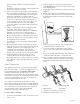
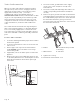
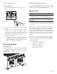
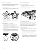
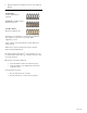
Table Of Contents

Page. 20
ignition module, require it to operate safely and
properly.
• Mount the receptacle securely to a wall stud, then seal
around the receptacle's housing.
• If the correct power supply circuit is not provided, it is
the responsibility and obligation of the installer and
user to have proper power supply connected. This
must be accomplished in accordance with all
applicable local codes and ordinances by a qualified
electrician. It is the responsibility of the installer to
ensure compliance of local codes. In the absence of
local codes and ordinances, the power supply
connection shall be in accordance with the National
Electric Code.
• Observe all governing codes and ordinances when
grounding. In the absence of these codes or
ordinances observe National Electrical Code ANSI/
NFPA No. 70 current issue. See the following
information in this section for grounding method.
• Electrical wiring diagrams and schematics have been
placed in the kick panel area of the range for access
by a qualified service technician.
• The ranges are to be connected to a 240/208 VAC
power supply.
• Dual Fuel models must be connected to the power
supply utilizing one of the following methods. For all
methods of connection, the length of the cord or
conduit/wiring must allow the unit to be slid
completely out of the cabinet without having to
unplug or disconnect the unit from the power supply.
• Recommended minimum free length of cord or
conduit is 4ft (1.2 m). Electrical installations and
grounding must be in accordance with all local codes
and ordinances, and/or the National Electric Code, as
applicable.
4-wire connection
This appliance must be connected to the power supply
with a listed (UL, CSA, ...) 3-POLE, 4-CONDUCTOR cord
kit rated 125/250 VOLTS, 50 AMPERES DEDICATED
CIRCUIT, and marked for use with ranges. It is the
responsibility of the installer to provide the proper wiring
components (cord, wires, etc.) and complete the electrical
connection as dictated by local codes and ordinances,
and/or the National Electrical Code.
The cord kit is required to be attached to the range
terminal block with a strain relief (not provided) which will
fit a 1'' (25.4 mm) diameter hole. If not already equipped,
the cord must also have 1/4'' (6 mm) faston closed-loop
lugs attached to the free ends of the individual
conductors, preferably soldered in place.
To wire a 4-wire connection
1. Locate the terminal block on the rear of the unit and
remove cover.
2. Remove upper nuts only from the terminal block
studs. DO NOT remove lower nuts which secure range
internal wiring leads.
3. If applicable, remove the 4-wire power cord from the
appliance.
4. Mount strain relief (not provided with range) into the
1'' (25.4 mm) diameter hole in the back panel located
below the terminal block. Route wires up through
strain relief.
5. Remove green ground screw and serrated washer
located beneath the terminal block.
6. Secure the neutral, grounded wire of the supply
circuit, to the center stud of the terminal block with
nut.
7. Secure the L1 (red) and L2 (black) power leads to the
outside terminal studs (brass colored) with nuts.
8. Secure the bare copper ground lead to the range
chassis using the ground screw and serrated washer.
Be sure that neutral and ground terminals do not
touch.
9. Tighten all connections securely and
10. Reinstall the terminal block cover.
a – Red/L1 b – Green/ground
c – White/neutral d – Black/L2
d
c
b
a