INSTALLATION INSTRUCTIONS For Thermador Professional® PRO-HARMONY™ Gas Ranges INSTRUCTIONS D’INSTALLATION Pour toutes cuisinières à gaz Thermador Professional® PRO-HARMONY™ Models P30 P36
Please Read Entire Instructions Before Proceeding IMPORTANT: INSTALLER: OWNER: Save these instructions for the Local Gas Inspector’s use. Please leave these Installation Instructions with this unit for the owner. Please retain these instructions for future reference. WARNING Disconnect power before installing. Before turning power ON, be sure that all controls are in the OFF position. IMPORTANT Local codes vary. Installation, gas connections and grounding must comply with all applicable codes.
Contents Important Installation Information ................. 1 Step 1: Ventilation Requirements................ 2 Step 2: Cabinet Preparation ................. 3 – 7 Step 3: Unpacking, Moving and Placing the Range ......................... 8 – 9 Step 4: Installing Anti-Tip Device ...... 10 – 11 Step 5: Gas Requirements and Hookup .... 12 Step 6: Electrical Requirements, Connection and Grounding ....................... 13 Step 7: Backguard Installation ..................
Important Installation Information GAS type verification CAUTION Verify the type of gas supplied to the location. Ensure that the appliance is connected to the type of gas for which it is certified. Ranges are certified for use with only natural gas or propane (LP) gas. Make certain the range matches the gas type available; these ranges are NOT convertible between gas types.
Step 1: Ventilation Requirements It is strongly recommended that a suitable exhaust hood be installed above the range. Downdraft ventilation should not be used. The table below indicates the Thermador hoods, by model number, that are recommended for use with all ranges. IMPORTANT: Ventilation hoods and blowers are designed for use with single wall ducting. However, some local building codes or inspectors may require double wall ducting.
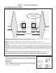
Step 2: Cabinet Preparation 1. The range is a free standing unit. If the unit is to be placed adjacent to cabinets, the clearances shown in Fig. 1 are required. The same clearances apply to island installations, except for the overhead cabinets, which must have a space wide enough to accept the flared island hood, as indicated in Fig. 1. 4. Any openings in the wall behind the range and in the floor under the range must be sealed. 5.
Step 2: Cabinet Preparation FIG. 1 Cabinet Clearances or 36" Wide Hood } 30" 36" or 42" for Island For 36" Ranges } 36" or 42" Wide Hood 42" or 48" for Island ® Min. Distance Between Overhead Cabinets of Combustible Material Ð 30" Range – 30" 36" Range – 36" 13" Max. Cabinet Depth ® ® ® } ® 18" Min. 36" from bottom of overhead Hood to cooking surface (40" min. if hood contains combustible materials ) ® For 30" Ranges Range width 30" or 36" ® CAUTION: See ® Figs. 2A, and 2B. 40" Min.
Step 2: Cabinet Preparation FIG. 2A - Side View FIG. 2B - Side View combustible materials 27 5/8" 26 1/2" combustible materials 12" min. to combustibles with island trim 40" min. to combustibles 40" min. to combustibles 10 3/4" 2 1/4" Pot and High Shelf Pan Shelf island trim 22" 9" 3" (36"*) (P36) Low Back Guard 6" (P304) (30"*) Countertop 24 5/8" 36 3/4" max. 35 7/8" min. 23 7/8" max. 36 3/4" max. 35 7/8" min.
Step 2: Cabinet Preparation GAS AND ELECTRIC SUPPLY FIG. 3A Gas & Electrical Supply Locations for All Gas Ranges 1 3/4" maximum protrusion from wall for gas or electrical supply gas supply zone electrical supply zone 8 1/2" 1 3/4" 6" 6" 6" 6" 30 1/4" (30" models) 36 1/4" (36" models) NOTE: If not already present, install gas shut-off valve in an easily accessible location. Make sure all users know where and how to shut off the gas supply to the range.
Step 2: Cabinet Preparation ELECTRICAL SUPPLY, ALL GAS RANGES Installation of the range must be planned so that the rough-in of the junction box for the receptacle will allow maximum clearance to the rear of the unit. FIG. 3B Wall Connection Power Cord & Receptacle 7 To minimize binding when the unit is connected to the receptacle or junction box, orient the receptacle and slide back into position.
Step 3: Unpacking, Moving and Placing the Range Chart A 30" Range 36" Range Shipping Weight 300 lbs. 335 lbs. Weight without packing materials 265 lbs. 300 lbs. Without door(s), burner caps, front kick panel and oven racks 142 lbs. 207 lbs. CAUTION Proper equipment and adequate manpower must be used in moving the range to avoid injury, and to avoid damage to the unit or the floor. The unit is heavy and should be handled accordingly. FIG.
Step 3: Unpacking, Moving and Placing the Range • Due to the weight, a dolly with soft wheels should be used to move this unit. The weight must be supported uniformly across the bottom (See Fig. 5). • After transporting the professional range by dolly close to its final location, the range can be tipped back and supported on the rear legs while the dolly is carefully removed. THE FLOOR UNDER FIG. 5- Dolly Positioning THE LEGS SHOULD BE PROTECTED. BEFORE PUSHING THE UNIT INTO POSITION.
Step 4: Installing Anti-Tip Device For all 30" and 36" ranges, an anti-tip device must be installed as per these instructions. WARNING RANGE TIPPING HAZARD • • • WARNING All ranges can tip and injury can result. To prevent accidental tipping of the range, attach it to the floor, wall or cabinet by installing the Anti-Tip Device supplied. A risk of tip-over may exist if the appliance is not installed in accordance with these instructions.
Step 4: Installing Anti-Tip Device 30" and 36" Ranges (Figures 6 and 7) Thermador Service Part No. 415078 600413 Qty. 4 1 • • • The anti-tip bracket may be attached to a solid wood cabinet having a minimum wall thickness of 3/4". The thickness of the wall or floor may require use of longer screws, available at your local hardware store. In all cases, at least two (2) of the bracket mounting screws must be fastened to solid wood or metal.
Step 5: Gas Requirements and Hookup Verify the type of gas being used at the installation site. As shipped from the factory, units are configured for use with only natural gas or propane (LP) gas. Make certain the range matches the type of gas available at this location. These ranges are NOT convertible between different types of gas.
Step 6: Electrical Requirements, Connection & Grounding • Before installing, turn power OFF at the service panel. Lock service panel to prevent power from being turned ON accidentally. Chart B: Electrical Supply Circuit Requirements • MODEL VOLTAGE CIRCUIT RATING FREQUENCY PHASE 304 366 364GL 364GE 120 VAC 120 VAC 120 VAC 120 VAC 10 Amps 10 Amps 10 Amps 20 Amps 60 Hz. 60 Hz. 60 Hz. 60 Hz.
Step 7: Backguard Installation 6” or 9” LOW BACK: 6” Low Back – included with 30” Pro Harmony Gas Range. Model GP36LB, 9” tall – for 36” Pro Harmony Gas Ranges. 22” High POT-and-PAN SHELF: Model GP30HS – for 30” Pro Harmony Gas Range. Model GP36HS – for 36” Pro Harmony Gas Ranges. 3” ISLAND TRIM: Model GP30IT – for 30” Pro Harmony Gas Range. Model GP36IT – for 36” Pro Harmony Gas Ranges. · The backguard must be attached before sliding the range into the final, installed position.
Step 8: Door Removal and Reinstallation CAUTION USE CAUTION WHEN REMOVING THE DOOR. THE DOOR IS VERY HEAVY. • Make sure oven is cool and power to oven has been turned off before removing the door. Failure to do so could result in electrical shock or burns. • The oven door is heavy and fragile. Use both hands to remove or replace the door. • Grasp only the sides of the oven door when removing or replacing it.
Step 9: Burner Test and Adjustment Install any loose components, such as burner caps and grates, that may have been removed earlier. Be certain that burner caps seat properly into the burner bases. Before testing operation of the appliance, verify that the unit and the gas supply have been carefully checked for leaks and that the unit has been connected to the electrical power supply. Turn the manual gas shut-off valve to the open position. FIG.
Step 9: Burner Test and Adjustment Test Oven Burners Flame Adjustment (if necessary): Remove the oven bottom cover. Remove the 4 screws on the sides and the 2 screws on the back, then slide the cover forward while lifting to clear the angled baffle plate mounted to the bottom of the cover. Tube-style gas burners used in Thermador© appliances have air shutter systems which are similar to the illustration in Figure 10, and can be adjusted using the following method (unless adjustment is not recommended).
INSTALLER CHECKLIST FINAL CHECK LIST ❑ Specified clearances maintained to cabinet surfaces. ❑ Unit Level – front to back – side to side. ❑ Burner caps positioned properly on sealed burner bases. ❑ All packaging material removed. ❑ Island trim or backguard attached. Backguard needed if horizontal clearance to combustible materials behind cooking surface is less than 12". ❑ Check door fit to oven cavity. Reinstall door if necessary (See door reinstallation procedure at the bottom of page 15.
NOTES
Veuillez lire toutes les instructions avant de poursuivre Important : Conservez ces instructions pour l’inspecteur local de la compagnie de gaz. Installateur : Veuillez laisser ces instructions d’installation avec l’appareil pour le propriétaire. Propriétaire : Veuillez conserver ces instructions pour consultation ultérieure. AVERTISSEMENT Coupez l’électricité avec d’installer l’appareil. Avant de remettre l’électricité, assurez-vous que toutes les commandes sont sur la position OFF.
Table des matières Informations importantes à propos de l'installation .......... 1 Chapitre 1 : Exigences pour la ventilation ....................... 2 Chapitre 2 : Préparation de l’emplacement ............... 3 – 7 Chapitre 3 : Déballage, manutention et mise en place de la cuisinière ........................................... 8 – 9 Chapitre 4 : Installation du dispositif antibascule.. . 10 – 11 Chapitre 5 : Exigences de l'alimentation du gaz et raccordement ...............................................
Informations importantes à propos de l'installation VÉRIFICATION DU TYPE DE GAZ MISE EN GARDE Vérifiez le type d'alimentation au gaz fourni du lieu d’installation. L’appareil doit être raccordé au type de gaz pour lequel il est certifié. Toutes les cuisinières sont certifiées pour une utilisation avec gaz naturel ou gaz propane seulement. Assurez-vous que la cuisinière correspond au type de gaz disponible ; ces appareils ne sont pas convertibles pour les types de gaz.
Chapitre 1 : Exigences pour la ventilation Il est fortement recommandé d’installer une hotte de ventilation appropriée audessus de la cuisinière. Une ventilation par contre-tirage ne devrait pas être utilisée. Le tableau ci-dessous énumère, par numéro de modèle, les hottes Thermador que l'on conseille d’utiliser avec les cuisinières. 1.
Chapitre 2 : Préparation de l’emplacement 1. La cuisinière est un appareil monobloc. Si elle est placée au milieu des armoires, les dégagements requis sont indiqués à la Figure 1. Les mêmes dégagements s’appliquent aux installations en îlot, excepté pour les armoires suspendues qui doivent laisser un espace suffisamment grand pour poser la hotte d’îlot évasée, comme le montre la Figure 1. 4.
Chapitre 2 : Préparation de l’emplacement FIG. 1 – Dégagement des armoires Profondeur max. de l’armoire : 33 cm (13") Largeur de la cuisinière 76,2 cm (30") ou 91,4 cm (36") } ® ® Cuisinières de 30" - 76,2 cm Cuisinières de 36" – 91,4 cm ® ® ® ® Distance minimum entre les armoires suspendues composées de matériaux combustibles ® Distance min. de 45,8 cm (18") Distance de 91,4 cm (36") entre le dessous de la hotte et la table de cuisson (101,6 cm (40")) min.
Chapitre 2 : Préparation de l’emplacement FIGURE 2A - Vue latérale FIGURE 2B - Vue latérale Matériaux combustibles Matériaux combustibles 27 5/8 po 26 1/2 po Min. 12 po aux combustibles avec garniture pour îlot Min. 40 po aux combustibles Min. 40 po aux combustibles 10 3/4po 2 1/4po Tablette à Tablette haute casserole Garniture pour îlot 22po 3 po 9po Dosseret bas (P36) (36")* 6po (P304) (30")* 24 5/8po 36 3/4 po max. 35 7/8 po min. Plan de travail Devant 23 7/8po max. 36 3/4po max.
Chapitre 2 : Préparation de l’emplacement ALIMENTATION DE GAZ ET ÉLECTRIQUE FIGURE 3A - emplacement de l'alimentation électrique et en gaz pour les cuisinières à gaz Bordure minimale de 1 3/4 po depuis le mur pour l'alimentation en gaz ou électrique Zone d'alimentation en gaz Zone d'alimentation électrique 8 1/2 po 1 3/4 po 6 po 6 po 6 po 6 po 30 1/4 po (Modèle 30 po) 36 1/4 po (Modèle 36 po) REMARQUE : Une soupape d'arrêt de gaz manuelle (si elle n'est pas déjà en place) doit être facilement access
Chapitre 2 : Préparation de l’emplacement Alimentation électrique pour toutes les cuisinières au gaz L’installation des cuisinières à gaz doit être planifiée de sorte que la boîte de dérivation pour la prise laisse le maximum d’espace à l’arrière de l’appareil. Ce point est particulièrement important si la boîte de dérivation murale se trouve juste derrière la boîte de dérivation de l’appareil une fois celui-ci installé.
Chapitre 3 : Déballage, manutention et mise en place de la cuisinière MISE EN GARDE Un équipement adapté manipulé par du personnel expérimenté doit être utilisé pour déplacer la cuisinière afin de ne pas endommager l’appareil ni le plancher. La cuisinière est lourde et repose sur des pieds réglables en acier. • Le poids approximatif de la cuisinière à l’expédition est celui qui est indiqué au Tableau A.
Chapitre 3 : Déballage, manutention et mise en place de la cuisinière • • • • • En raison du poids de la cuisinière, il convient d’utiliser une plate-forme à roulettes souples pour la déplacer. Le poids doit être uniformément réparti sur la plate-forme (voir Figure 5). FIG.
Chapitre 4 : Installation du dispositif antibascule Pour toutes les cuisinières de 76,2 cm (30") et de 91,4 cm (36"), un dispositif antibascule doit être installé conformément aux instructions suivantes. AVERTISSEMENT DANGER DE BASCULEMENT • • • AVERTISSEMENT Toutes les cuisinières peuvent basculer et blesser quelqu’un. Pour éviter un basculement accidentel, elles doivent être attachées au sol, au mur ou à une armoire au moyen de l’installation du dispositif antibascule qui vous est fourni.
Chapitre 4 : Installation du dispositif antibascule Cuisinières à gaz de 30 po et 36 po (Figures 6 et 7) Référence pièce détachée Thermador 415078 600413 Quantité 4 1 Description Vis Phillips no 10 3,81 cm (1-1/2 po) Patte antibascule, montage au sol INFORMATIONS IMPORTANTES À PROPOS DE L’INSTALLATION - Pour les murs ou les sols de type préfabriqué, carton-plâtre ou autres matériaux mous, percez des trous de 4,8 mm (3/16") à une profondeur minimum de 4,45 cm (1-3/4") puis enfoncez les ancrages en plastiq
Chapitre 5 : Exigences de l'alimentation du gaz et raccordement Vérifiez le type de gaz utilisé à l’endroit où la cuisinière est installée. Celle-ci sont préparéé à l’usine avant expédition pour être alimentée seulement par du gaz naturel ou du gaz propane. La cuisinière doit correspondre au type de gaz utilisé sur le site. La cuisinière N'EST PAS convertible entre les différents types de gaz.
Chapitre 6 : Exigences pour l’alimentation électrique, le branchement et la mise à la terre • Avant d’intervenir sur l’appareil, débranchez toujours le cordon d’alimentation électrique de la prise murale. Verrouiller le panneau de service pour empêcher la mise en circuit accidentelle. Tableau B : Exigences pour les circuits d’alimentation électrique • • MODÈLE TENSION INTENSITÉ DU CIRCUIT FRÉQUENCE 304 120 VAC 10 Amps 60 Hz.
Chapitre 7 : Installation du dosseret MODÈLE BAS 6 OU 9 PO : Modèle bas 6 po – compris avec la cuisinière à gaz Pro avec quatre (4) vis à tête Torx sur les panneaux Harmony 30 po. latéraux de la cuisinière et huit (8) vis au rebord inférieur et la zone autour du ventilateur de Modèle GP36LB – 9 po de haut ; pour cuisinières à gaz refroidissement. Voir les 12 emplacements indiqués Pro Harmony 36 po. par les flèches.
Chapitre 8 : Retrait et installation de la porte MISE EN GARDE FAIRE ATTENTION POUR RETIRER LA PORTE, ELLE EST LOURDE. • S'assurer que le four est froid et que l'alimentation est hors circuit avant de retirer la porte. Sinon, il peut en résulter un choc électrique ou des brûlures. • La porte est lourde et fragile. Utiliser les deux mains pour enlever ou installer la porte. • Saisir les côtés de la porte pour enlever ou installer la porte.
Chapitre 9 : Test et réglage de brûler Installer tout composant lâche, tels capuchons et grilles de brûleurs, ayant été retirés précédemment. S'assurer que les capuchons de brûleurs sont adéquatement placés sur les bases des brûleurs. Avant de vérifier le fonctionnement de l'appareil, vérifier qu'il n'y a aucune fuite à l'appareil et à la soupape de gaz; que l'appareil est branché sur l'alimentation électrique. Ouvrir la soupape d'arrêt de gaz manuelle. FIG.
Chapitre 9 : Test et réglage de brûler Vérifier les brûleurs du four Réglage de flamme (au besoin): Enlever le couvercle du fond du four. Enlever les 4 vis sur les côtés et les 2 à l'arrière, puis faire glisser le couvercle vers l'avant en le soulevant pour dégager la plaque protectrice en angle du fond du couvercle.
Liste de vérification pour l’installateur LISTE FINALE VÉRIFICATION DE ALIMENTATION EN GAZ FONCTIONNEMENT ❑ Les distances spécifiées entre l’appareil et les armoires adjacentes sont respectées. ❑ Le nivellement de l’appareil d'avant vers l'arrière, et d'un côté à l'autre a été effectué. ❑ Les chapeaux de brûleurs ont bien placés sur les bases. ❑ Tous les matériaux d’emballage ont été enlevés.
REMARQUES
Specifications are for planning purposes only. Refer to installation instructions and consult your countertop supplier prior to making counter opening. Consult with a heating and ventilating engineer for your specific ventilation requirements. For the most detailed information, refer to installation instructions accompanying product or write Thermador indicating model number. We reserve the right to change specifications or design without notice. Some models are certified for use in Canada.