INSTALLATION GUIDE GUIDE D'INSTALLATION GUIA DE INSTALACION Model/Modele/Modelo T24UW925LS T24UW925RS T24UW915LS T24UW915RS T24UW905LP T24UW905RP Glass Door Wine Reserve Cellier avec porte en verre Enfriador de vinos Page | 1
IMPORTANT: Before you begin, read these instructions completely and carefully. INSTALLER: Please leave this manual with owner for future reference. OWNER: Save these installation instructions for local electrical inspector’s use and for future reference. Table of Contents Important Safety Instructions ….…………. 3 - Inspect the Wine Reserve Tools needed for installation …………….. 4 Materials supplied …………….………….… 4 Installing the appliance …………………….
Important Safety Instructions READ AND SAVE THESE INSTRUCTIONS! These installation instructions are intended for use by qualified installers. In addition to these instructions, the appliance shall be installed: • In the United States, in accordance with the National Electric Code/State and municipal codes and/or local codes. • In Canada, in accordance with the Canadian Electric Code C22.1 – latest edition/Provincial and Municipal codes and/or local codes.
Tools needed for installation Tape Measure Philips Screwdriver Level These are the tools that you may need for the installation of the appliance. However, if you need to modify the counter or cabinetry to fit the unit, you may need other tools to make counter/cabinetry modifications before installing the appliance. Materials supplied Anti-tip-bracket. 2 pieces. Screws: 2 pieces.
Installing the appliance Most of the installation work must be done before the Wine Reserve is moved into place. Have a qualified technician install and connect the appliance according to the enclosed installation instructions. WARNING: Do not install this appliance: - Outdoors - In an environment with dripping water - In rooms where there is a risk of frost Transporting The appliance is heavy and must be handled with caution during transportation and installation.
Installation location A dry, well ventilated room is suitable as an installation location. The installation location should not be exposed to direct sunlight and not placed near a heat source, e.g. a cooker, radiator, etc. If installation next to a heat source is unavoidable, use a suitable insulating plate or observe the following minimum distance from the heat source: ▪ ▪ ▪ To electric or gas oven/range 1¼” (3 cm). To an oil or coal-fired cooker 1113/16” (30cm).
TOP VIEW OPEN RIGHT SWING TOP VIEW OPEN LEFT SWING Page | 7
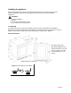
Installing Side-by-Side The appliance can be installed next to another Thermador appliance. Follow the next dimensions and notes for the correct installation of the appliance in a side-by-side layout. NOTE: Before placing the unit into the niche, adhere the Insulating Foam (included with the product) on the side of the unit that will be placed next to the additional appliance.
Do not place one appliance with Right Hinge next to an appliance with a Left Hinge. 607mm 23 7/8 in ! 1226mm 48 1/4 in 607mm 23 7/8 in 13mm ½ in (MÍNIMUM) Interference Ventilation The Wine Reserve unit is ventilated only at the Toe-Kick in the base. Never cover that area or place anything in front of it. Otherwise the refrigeration cooling performance will be affected and the unit must work harder increasing power consumption.
Electrical connection WARNING: These installation instructions are intended for use by qualified installers. WARNING: Avoid the risk of an electric shock! Insert into a grounded receptacle. Never remove grounding phase. Do not use any adapters. Do not use any extension cords. WARNING: It is the customer’s responsibility to ensure that the appliance installation is in compliance with all national and local electrical codes and ordinances.
WARNING: Never connect the appliance to electronic energy saver plugs. This appliance can be used with mains and sine-controlled inverters. Main controlled inverters are used for photovoltaic systems which are connected directly to the national grid. Sine-controlled inverters must be used for isolated applications (e.g. on ships or in mountain lodges) which are not connected directly to the national grid. The appliance requires a 3-pole socket. The socket should be connected by a qualified electrician only.
2. Grab the stopper pin from the bag included with this appliance and insert into the hole as shown: 3. Push firmly to ensure the stopper pin has locked into the hinge. Now, the door opens only 90°.
Installing the anti-tip-brackets The appliance includes two anti-tip-brackets. If your cabinetry is not designed for the specific dimensions of your appliance, or if you plan to use the appliance as a free-standing unit, you should use these brackets to avoid your appliance tilting due to unbalanced overweight situations where the door is open and several Wine Racks are pulled out. WARNING To avoid the appliance tilting due to unbalanced overweight do not pull out all the Wine Racks at the same time.
3. Peel the adhesive foam and paste the anti-tip-bracket at both sides on the back of the appliance as shown in the illustrations. Paste the anti-tip-bracket to the back of the appliance. 4. With the anti-tip-brackets pasted on the back of the appliance, slide the appliance to the wall until the anti-tip-bracket is touching the wall. Using the screws provided, fasten the anti-tip-bracket to the wall for both sides. NOTE: Do not fasten the unit to drywall. Be sure to attach the unit to a solid surface.
For under counter use 1. Consider the distance necessary for the appliance to be flush with the front of your cabinetry. 600mm 23 5/8” Unit Thermador Wine Reserve Top View . 2. Take the measurement from the top of the cabinet of the unit to the bottom of the counter. The measurement X”(mm) may vary depending on the design of the counter, extension of the legs of the product, etc. Distance = X” (mm) NOTE: the Distance = X” (mm) may vary depending on the design of your cabinetry. 3.
4. Peel the adhesive foam and paste the anti-tip-bracket at the front on the top of the cabinet of the appliance, near the corners as shown in the picture: Paste the anti-tip-bracket near the corners. 5. Slide the appliance into the cabinet until the front of the appliance is flush with the front of the cabinetry. Check that nothing interferes or obstructs the anti-tip-bracket while sliding under the counter. Slide the appliance into the cabinet until the front surfaces are flush.
Installing the overlay frame (For T24UW905LP and T24UW905RP models only) If you plan to install a custom overlay frame, you will need to create the frame yourself or consult a qualified cabinetmaker or carpenter. A full sized template for easier hole pattern marking is included in the manual package. IMPORTANT: - The thickness of the overlay frame must be ¾” (19mm). - Overlay frame must not weigh more than 10lbs (4.54kg). - Overlay frame weighing more than recommended may cause damage to your appliance.
IMPORTANT: It is recommended to install the custom overlay frame with the help of another person. 1. Install the custom handle of your preference on the overlay frame before installing the frame on the door. - Every custom handle is different and it is the responsibility of the customer to make the necessary adjustments to place the handle on the overlay frame.
3. Remove the door gasket from the corners, by pulling it gently until the four screws are visible. Then remove the two screws further to the corner. The two holes shown on the below illustration must be accessible to screw (install) the custom overlay frame to the door. There should be 8 accessible holes in total, two per corner. NOTE: It is not necessary to remove the entire gasket from the door, just from the corner, enough to access to the screws. Remove the screws to leave these holes 4.
5. Once the overlay frame is securely attached to the door with the 8 screws, put the gasket back in its place pressing it against the door until all is even and firm into its channel. Put gasket back in its place 6. Now, the overlay frame is ready.
Customer Service Information If service becomes necessary, contact your dealer or an authorized service center. Do not attempt to repair the appliance yourself. Any work performed by unauthorized personnel may void the warranty. If problem persists, take the following steps (in the order listed below) until the problem is corrected to your satisfaction. 1. Contact your dealer or the Thermador Authorized Servicer in your area. 2. E-mail us from the Customer Service section of our web site, www.Thermador.com.
Addendum A. Detailed dimensions for Overlay Frame. Ø5/16” (8mm) Hole. Depth: ¼” (7mm) Page |22 Important Cutout depth: 3/16” (4mm) - The thickness of the overlay frame must be ¾” (19mm). Ø1/2” (12mm) Hole. Depth: ¼” (7mm) - Overlay frame must not weigh more than 10lbs (4.54kg).
Data Rating Label The data rating label shows the model and serial number of your appliance. It is located in the interior of the cabinet, at the opposite side of the hinge. Service Information For handy reference, copy the information in the form below from the data rating located in the interior of the cabinet, at the opposite side of the hinge. Keep your invoice for Warranty validation.
PN: ARAH1E105030 / 8001087775 T24UW925LS T24UW925RS T24UW915LS T24UW915RS T24UW905LP T24UW905RP Page |24 04/2021 Printed in Mexico Impreso en México Imprime au Mexique