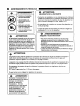
Th dor ® CORPORATION 6D 00 INSTALLATION INSTRUCTIONS MANUAL PROFESSIONAL RANGES ALL-GAS MODELS - PRG304, PRG36 ANqTPRG48. DUAL-FUEL MODELS - PRDS304, PRDS36 AND~PRDS48 PLEASE READ ENTIRE INSTRUCTIONS BEFORE PROCEEDING. IMPORTANT: LOCAL CODES VARY. INSTALLATION, ELECTRICAL CONNECTIONS, GAS CONNECTIONS. AND GROUNDING MUST COMPLY WITH ALL APPLICABLE CODES. ill) —11 IMPORTANT: Save these instructions for the Local Electrical Inspector's use.
IMPORTANT INSTALLATION INFORMATION Model PRDS484GG INTRODUCTION (Shown with Low Back Guard Model PRS48LB) WARNING: Improper The Thermador Professional* Ranges are free standing units installation, adjustment, alteration, service or main available in a number of configura tenance can cause injury or tions. Model PRG304 is equipped with four sealed gas surface burn ers, a large capacity gas oven with property damage. Refer to this manual.
AVERTISSEMENTS EN FRANCAIS Thermadar CORPORATION For Residential Use Only ® ALL-GAS MODELS - PRG304 AND PRG36, DUAL FUEL MODELS PRDS304, PRDS36 AND PRDS48 CET MAN U EL CONTEN IT AVERTISSEMENTS EN FRANCAIS AVERTISSEMENT: Couper le courant avant d'installer. Avant de mettre EN MARCHE, soyez certain que tous les controles sont dans la position ARRETE. AVERTISSEMENT: DANGER DE RENVERSEMENT DE LA CUISINIERE ^AVERTISSEMENT: L'lnstallatlon inexacte. rajustement.
AVERTISSEMENTS EN FRANCAIS ADVEHnBfflJVIENlY s • TOUTESLESCUISINIERES PEUVENTRENVERSER • LESBLESSURESAUX PERSONNES PEUVENT R&ULTER • INSTALLER L'APPAREIL ANTl-RENVERSER EMALLE AVEC LA CUISINIERE • VOIR LES INSTRUCTIONS ^INSTALLATION LES DEGATS DE LA PROTRIETE • Contacter un installateur ou un entrepreneur du batiment quallfie pour determiner la methode convenable pour forer les trous a traverse du materiau du mur du plancher (tel que ie carreau ceramique, le bols feuillu, et c.
IMPORTANT INSTALLATION INFORMATION /^IMPORTANT: ity of this unit, particular attention should be paid to the hood and duct work installation to assure it meets local building codes. To eliminate risk of burns or fire caused by reaching over heated surface units, cabinet storage located above the surface units should be avoided. All ranges must be installed with a backguard. Models PRG304 and PRDS304 are shipped from the factory with a standard 9" backguard.
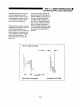
STEP 2: CABINET PREPARATION 1. The range is a free standing 4. unit. If the unit is to be placed adjacent to cabinets, the clearances shown in Fig. 1 are required. The same clearances apply to island installations, except for the overhead cabi nets, which must have a space 5. 6. wide enough to accept the flared island hood, as indicated The PRDS48 Ranges must be placed with the oven door projecting out from the cabinet face.
STEP 2: CABINET PREPARATION FIG. 2a FIG. 2b Side View 30" Ranges - Com bustible //// Side View 36" and 48" Ranges //// //// ///S //// -—Com- Materials & 28-3/4' 27-5/8" Optional High Shelf AY Mln. to Combustibles A 42" Mln. to Std. Combustibles A __ Low Back Guard (Provided with 30" Range) Clearance s/ss ss/s // 26-3/8' »► +— 24-3/8" *- 16-1/2"—> A as defined in the 'National Fuel Gas Code* (ANSI Z223.1. Current issue). FIG.
STEP 2: CABINET PREPARATION GAS AND ELECTRIC SUPPLY ZONES: FIG. 3a Gas & Electrical Supply Zone for PRG304, PRG36 & PRG48 All-Gas Ranges 5/8" Flex Line to Typical placement shown. Other placement of Gas Appliance Three-Prong, with a power supply cord with a three-prong grounding plug. IT MUST BE PLUGGED 120 VAC Receptacle Supply and Electrical Receptacle within the Electrical and Gas Supply The All-Gas Ranges are factory equipped INTO A MATING, GROUNDING-TYPE.
STEP 2: CABINET PREPARATION I ELECTRICAL SUPPLY, DUAL FUEL RANGES Installation of Dual Fuel ranges This is especially critical if the must be planned so that the junction box in the wall will be rough-in of the junction box for directly behind the junction box on the unit when the unit is the receptacle or conduit connec tion will allow maximum clear ance to the rear of the unit. installed. Refer to Figures 16 and 16a for location of junction box on unit.
STEP 3: UNPACKING, MOVING AND PLACING THE RANGE <► CAUTION: Proper equipment and adequate manpower must be used in moving the range Chart A 30" Range 36" Range 48" Range Shipping Weight 335 lbs. 444 lbs. 584 lbs. Weight without 285 lbs. 390 lbs. 524 lbs. 215 lbs. 295 lbs. 395 lbs. to avoid damage to the unit packing materials or the floor. The unit is heavy and rests on adjust able steel legs.
STEP 3: UNPACKING, MOVING AND PLACING THE RANGE Due to the weight, a dolly with soft wheels should be used to move this unit. The weight must be supported uniformly across the bottom (See Dolly Positioning Range Must be Fig. 7). Uniformly Supported by Braces Provided on Bottom yof Range After transporting the professional range by dolly close to its final location, the range can be tipped back and supported on the rear legs while the dolly is carefully removed.
■ STEP 4: INSTALLING ANTI-TIP DEVICE For all 30" and 36" ranges, an anti-tip device must be installed as per these instructions. WARNING RANGE TIPPING HAZARD • ALL RANGES CAN TIP All ranges can tip and injury could result. To prevent accidental tipping of the range, attach it to the wall, floor or INJURY TO PERSONS COULD RESULT cabinet by installing the Anti-Tip Device INSTALL ANTI-TIP supplied. • A risk of tip-over may exist if the appli ance is not installed in accordance with these instructions.
STEP 4: INSTALLING ANTI-TIP DEVICE Parts Required for Installation of Anti- Tip Device: PRG304 and PRG36 All Gas Ranges (Figures 9 and 10) Thermador Part No. Qty Description 15-10-916 4 Screw. Phillips,#10 x 1-1/2' 15-10-771 1 Anti-Tip Channel, Adjust FIG. 10 Adjustable Anti-Tip Channel PRG304 and PRG36 All-Gas Ranges able. PRG 15-10-772 1 Mounting Bracket. PRG 15-10-909 1 Bolt. Hex Head. l/4"-20x ■5-1/2" 15-10-910 1 Nut. Hex. 1/4-20 15-10-911 2 Washer. Flat.
STEP 4: INSTALLING ANTI-TIP DEVICE PRG304 AND PRG36 All-Gas Ranges (Figures 9, 10, 12a 12b and 13) STEP A: Determine the best location for the PRG Mounting Bracket. The bracket may be mounted to the wall or floor behind the range, offset from either the left or right side wall by 2-3/4" for model PRG304 or FIG. 12a PRG36 Wall Mount (0" Clearance) PLAN VIEW 4-5/8" for Model PRG36.
STEP 4: INSTALLING ANTI-TIP DEVICE STEP H: Using the l/4"-20 x 1/2" Hex Head Bolt, Hex Nut and two (2) Flat Washers, FIG. 13 PRG36 Floor Mount securely attach the Adjustable Anti-Tip PLAN VIEW Channel to the existing hole in the flange located at the bottom rear of the range. (There are two (2) holes in the range flange, Anti-Tip Channel so be certain to select the hole that is on the same side as the mounting bracket.
STEP 4: INSTALLING ANTI-TIP DEVICE STEP B: Set the bracket on the floor and turn it until it is oriented properly. The long channel should be on the top with the free end facing towards you, one set of mounting FIG. 14 PRDS Wall Mount flanges should be resting horizontally on PLAN VIEW the floor, and the other set of mounting flanges should be positioned vertically facing the rear. STEP C: Slide the bracket to the desired position. Note that the minimum (dim. "A") and maximum (dim.
STEP 5: GAS REQUIREMENTS AND HOOKUP Verify the type of gas being used at the installation site. As shipped from the factory, all units are configured for use on natural gas. For use with propane gas, the unit must be converted. Field conversion for use with propane must only be done by qualified service person nel. Contact the dealer where the unit was purchased or Thermador (800/735-4328). The field conversion kit for all Professional Series ranges is Thermador Model STARLPKIT.
STEP 6: ELECTRICAL REQUIREMENTS, CONNECTION & GROUNDING Prior to servicing appliance, always disconnect appliance electrical supply cord, if so equipped, from wall receptacle. If appliance is hard wired to power supply, disconnect Dual Fuel range models PRDS304. PRDS36 and proper circuit breaker or disconnecting the proper fuse. PRDS48 can be cord-con nected or hard-wired to the power supply, as described on Gas range models PRG304, PRG36 and PRG48 must be Page 17.
STEP 6: ELECTRICAL REQUIREMENTS, CONNECTION & GROUNDING Dual Fuel models PRDS304, PRDS36 and PRDS48 must be connected to the power supply utilizing one of the following methods. For all methods of connection, the length of the cord or conduit/wiring must allow the unit to be slid completely out of the cabinet without having to unplug or disconnect the unit from the power supply. Recommended minimum free length of cord or conduit is four feet.
STEP 6: ELECTRICAL REQUIREMENTS, CONNECTION & GROUNDING A 3 or 4 conductor supply may be connected to the terminal block. A 4 conductor supply shall be used only when the range is installed in a mobile home or where local codes do not permit grounding through the neutral. FIG.17 Conductor Securement Upper Nut ^-Cupped Washer *"- Supply Wire lat Washer 3 WIRE LEAD CONNECTION 1. Remove upper nuts only from the terminal block studs. Do not remove nuts which secure range internal wiring leads. 2.
STEP 6: ELECTRICAL REQUIREMENTS, CONNECTION & GROUNDING Recommended Grounding Method - All-Gas Models PRG304, PRG36 and PRG48 The 30," 36" and 48" all-gas ranges are factory equipped with a power supply cord with a three-prong grounding plug (with polarized parallel blades). IT MUST BE PLUGGED INTO A MATING GROUNDING TYPE RECEPTACLE THAT IS CONNECTED TO A CORRECTLY POLARIZED 120 VOLT CIRCUIT. (See Fig. 19).
STEP 6: ELECTRICAL REQUIREMENTS, CONNECTIONS & GROUNDING CASE 2: Electrical Connections and Grounding - with a 4-Conductor Power Supply (to be used only when local codes do not permit grounding through the neutral). Secure the neutral (white) wire of the supply circuit to the neutral terminal of the NEMA 14-50R recep tacle. Connect the LI (black) and the L2 (red) hot leads to the other terminals on the NEMA and connected to the box. per the instructions.
STEP 7: BACKGUARD INSTALLATION INSULATION AND RETAINER REMOVAL Before the backguard can be assembled onto Model PRDS304. PRDS36 and PRDS48 Ranges, the insulation FIG. 22a retainer and the insulation must be removed to avoid interference. This insulation is not required on the PRDS304, PRDS36 and PRDS48 models. The High Shelf Back Trim is shown. The procedure is the same for Island Trim or Low Back Trim Step 1 Remove the four (4) screws holding in insulation retainer. See Fig. 22a.
STEP 8: TEST AND ADJUSTMENT FIG. 23 PROPER FLAME (APPROX.) The gas oven infra-red broiler burner has no air shutter and is not adjustable when used Griddle. Grill, & Gas Oven Burners with natural gas. When used on propane gas, an air shutter is attached, but it is not Flame Height •H" 3urner Natural Gas Propane Gas Griddle 3/4" 3/4"to 1" Grill 1/4" 1/2" Gas oven 1-1/2" to 2" 1-1/2"to 3" adjustable.
INSTALLER CHECKLIST FINAL CHECK LIST □ a Placement of unit. □ Specified clearances maintained Manual gas shut off valve installed in an accessible location (without requiring removal of range). to cabinet surfaces. LJ Burner caps positioned properly seated (not all models). Refer to □ Gas supply pressure does not details. Use & Care Manual for Grill on sealed burner bases. ELECTRICAL All packaging material removed.
NOTES Page 24
NOTES Page 25
THERMADOR® is a leading manufacturer of Convection Micro Thermal Ovens. Convection Thermal Ovens. Thermal Electric Ovens, Warming Drawers. Free-Standing and Slide-In Ranges. Steel Gas ExtraLow5 Cooktops. Steel Gas Cooktops, Glass Gas ExtraLowCooktops, Glass Gas Cooktops. Glass Ceramic Gas Cooktops. GlassCeramic Dual-Fuel Cooktops, Glass Ceramic All-Radiant Cooktops. Glass Ceramic Halogen Cooktops. Electric Cooktops. Professional All Gas Ranges and Cooktops, Professional Dual-Fuel Ranges.