
Manual

A
TTPSales@thermasys.com 262.554.8330 www.thermaltransfer.com
108
FLUID COOLING
|
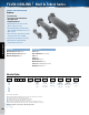
Shell & Tube A Series
WATER COOLED A
COPPER & STEEL CONSTRUCTION
Features
n
ITT Interchange
n
B or C Series is Recommended for
New Applications
n
Competitively Priced
n
Optional Non-Ferrous Construction
(Water-to-Water Service)
n
Optional 90/10 Copper Nickel Cooling
Tubes and Bronze End Bonnets for Sea
Water Service
n
NPT, SAE O-Ring, SAE Flange, or BSPP
Shell Side Connections Available
n
End Bonnets Removable for Servicing
n
Mounting Feet Included (May be
Rotated in 90° Increments)
Ratings
Maximum Shell Pressure 300 psi
Maximum Tube Side Pressure 150 psi
Maximum Temperature 300° F
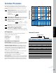
How to Order
Model Size Selected
Tube
Diameter
Code
4 - 1/4”
6 - 3/8”
Tubeside
Passes
0 - One Pass
T - Two Pass
F - Four Pass
–
Baff le
Spacing
Shell
Material
Blank - Steel
BR - Brass
Cooling
Tube
Material
Blank - Copper
CN - CuNi
End
Bonnet
Material
Blank - Cast Iron
B - Bronze
Zinc
Anodes
Blank - None
Z - Zinc
– –
–
––
–
–
Model
Series
SA
SAF
A
AS
AM
AF
AFM
Materials
Tubes Copper
Hubs & Tubesheets Steel or Brass
Shell Steel
B a f f l e s B r a s s
End Bonnets Cast Iron
Mounting Brackets S t e e l
Gaskets Nitrile Rubber/Cellulose Fiber
Nameplate Aluminum Foil
SA = NPT Shell side, NPT Tube
SAF = SAE 4 Bolt Flange (with UNC threads) Shell side connections; NPT Tube side connections
A = NPT Shell side connections; NPT Tube side connections
AS = SAE O-Ring Shell side connections; NPT Tube side connections
AM = BSPP Shell side connections; BSPP Tube side connections
AF = SAE 4 Bolt Flange (with UNC threads) Shell side connections; NPT Tube side connections
AFM = SAE 4 Bolt Flange (with Metric threads) Shell side connections; BSPP Tube side connections
SAE flanges available on some models. Consult factory for details.