
Manual


A
www.thermaltransfer.com TTPSales@thermasys.com 262.554.8330
113
WATER COOLED A
Caution : Incorrect installation can cause this product to fail prematurely, causing the
shell side and tube side fluids to intermix.
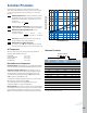
Maximum Flow Rates
5
4
3
2.5
2
1.5
1
.8
.7
.6
.5
50 60 70 80 100 150 200 250 300 400 500
A
B
OIL VISCOSITY - SSU
VISCOSITY CORRECTION
Selection Procedure
Performance Curves are based on 100SSU oil leaving the cooler 40°F
higher than the water temperature used for cooling. This is also referred to
as a 40°F approach temperature. Curves are based on a 2:1 oil to water
flow ratio.
Step 1 Determine the Heat Load. This will vary with different systems,
but typically coolers are sized to remove 25 to 50% of the input
nameplate horsepower. (Example: 100 HP Power Unit x .33 = 33
HP Heat load.)
If BTU/Hr. is known: HP =
BTU/Hr
2545
Step 2 Determine Approach Temperature. Desired oil leaving cooler °F
– Water Inlet temp. °F = Actual Approach (Max. reservoir temp.)
Step 3 Determine Curve Horsepower Heat Load. Enter the
information from above:
Horsepower heat load x 40 x Viscosity
Curve
Actual
Correction A
=
Horsepower
Approach
Step 4 Enter curves at oil flow through cooler and curve horsepower.
Any curve above the intersecting point will work.
Step 5 Determine Oil Pressure Drop from Curves:
j = 5 PSI; M = 10 PSI; l = 20 PSI. Multiply pressure drop from
curve by correction factor B found on oil viscosity correction curve.
Oil Temperature
Oil coolers can be selected using entering or leaving oil temperatures.
Typical operating temperature ranges are:
Hydraulic Oil 110°F - 130°F
Hydrostatic Drive Oil 130°F - 180°F,
Bearing Lube Oil 120°F - 160°F
Lube Oil Circuits 110°F - 130°F.
Desired Reservoir Temperature
Return Line Cooling: Desired temperature is the oil temperature leaving the
cooler. This will be the same temperature that will be found in the reservoir.
Off-Line Recirculation Cooling Loop: Desired temperature is the oil
temperature entering the cooler. In this case, the oil temperature change
must be determined so that the actual oil leaving temperature can be
found. Calculate the oil temperature change (oil sT) with this formula:
Oil sT = (BTU’s/Hr.) / (GPM Oil Flow x 210).
To calculate the oil leaving temperature from the cooler, use this formula:
Oil Leaving Temp. = Oil Entering Temp – Oil sT.
This formula may also be used in any application where the only
temperature available is the entering oil temperature.
Oil Pressure Drop: Most systems can tolerate a pressure drop through the
heat exchanger of 20 to 30 PSI. Excessive pressure drop should be avoided.
Care should be taken to limit pressure drop to 5 PSI or less for case drain
applications where high back pressure may damage the pump shaft seals.
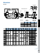
Example Model No.
A - 1024 - 2 - 6 - F
Unit Baff le Shell Side Tube Side (GPM)
Size Spacing (GPM) O T F
400 .75, 2 7, 19 18 – –
608 1, 2 14, 29 48 24 12
614 1.5, 4 21, 29 48 24 12
624 2, 4 29 48 24 12
814 1.5, 3 29, 57 87 44 22
824 & 836 2, 4 38, 69 87 44 22
1014 1.5, 3 32, 64 146 73 37
1024 & 1036 2, 4 42, 69 146 73 37
1224 2, 4 51, 103 224 112 56
1236 & 1248 3, 6 77, 115 224 112 56
1260 4, 6 103, 115 224 112 56
1624 2, 6 66, 200 280 140 70
1636 & 1648 3, 6 100, 200 280 140 70
1660 & 1672 4, 6 133, 200 280 140 70