Electric Boilers MINI ULTRA Models from 3 kW to 12 kW : 208/240V single phase INSTALLATION & OPERATING MANUAL Your MINI ULTRA Electric Boiler has been carefully assembled and factory tested to provide years of trouble-free service. The following information and safety measures are provided to enable proper installation, operation, and maintenance of this product. It is imperative that all persons who are expected to install, operate or adjust this boiler should read these instructions carefully.
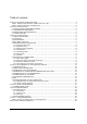
Table of contents Section 1: TECHNICAL SPECIFICATIONS.............................................................................................. 4 1 Table 1: Ratings & Specifications at 208 & 240**Vac / 1ph ................................................................. 4 Table 2 : Boiler connections and dimensions ....................................................................................... 4 Section 2: INTRODUCTION.............................................................................
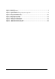
Figure 1 : Dimensions.............................................................................................................................. 1 Figure 2 : Mounting positions ................................................................................................................... 7 Figure 3 : Typical piping lay-out ............................................................................................................... 7 Figure 4 : Typical installation on high temperature application ..
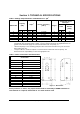
Section 1: TECHNICAL SPECIFICATIONS Table 1: Ratings & Specifications at 208 & 240**Vac / 1ph1 MINI ULTRA • • Capacity (KW) Amps 2 208 V 240 V 208 V 240 V 2.2 3 10.9 12.5 3.4 4.5 16.3 18.9 4.5 6 21.8 25.0 5.6 7.5 27.2 31.2 6.7 9 32.6 37.5 9 12 43.5 50.0 3 4.5 6 7.5 9 12 • Suggested size at 3 240V/1ph. Electric element(s) (240 V) Stages 1 x 3 KW 1 x 4.5 KW 2x 3 KW 1 x 3 KW + 1 x 4.5 KW 2 x 4.5 KW 2 x 6 KW 1 1 1 2 2 2 Breaker (Amp.
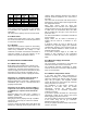
! General Safety Precautions Be sure to read and understand the entire Installation & operation manual before attempting to install or to operate this water heater. Pay particular attention to the following General Safety Precautions. Failure to follow these warnings could cause property damage, bodily injury or death. Should you have any problems understanding the instructions in this manual, STOP, and get help from a qualified installer or technician.
Section 3 : INSTALLATION ! WARNING The manufacturer’s warranty does not cover any damage or defect caused by installation, or attachment, or use of any special attachment other than those authorized by the manufacturer into, onto, or in conjunction with the water heater. The use of such unauthorized devices may shorten the life of the boiler and may endanger life and property. The manufacturer disclaims any responsibility for such loss or injury resulting from the use of such unauthorized devices 3.
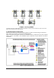
Figure 2 : Mounting positions *In position #5 and #6: on boilers MINI ULTRA 3 & 4.5kW , the heating element located in the upper section of the boiler must be relocated into the lower opening. 3.4 BOILER WATER CONNECTIONS Make sure you connect the accessories and the piping to the proper connection fittings as indicated at figure 2 above and according to the selected mounting position.
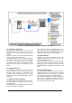
Figure 4 : Typical installation on high temperature application 3.4.1 Pressure relief valve This component supplied with the unit must be installed directly to the boiler housing to the appropriate connection according to the mounting position. Connect the outlet of the relief valve downward to a safe location in case of discharge. The piping diameter used for the discharge piping shall not be smaller than that of the valve outlet.
Model 3 4.5 6 7.5 9 12 Diff.10°F usgpm 2.0 3.0 4.1 5.1 6.1 8.2 Diff. 20°F usgpm 1.0 1.5 2.0 2.5 3.0 4.1 Boiler press. loss Insignificant Insignificant Insignificant Insignificant Insignificant Insignificant Your heating wholesaler shall be in good position to recommend the appropriate model for your application. The pump motor capacity must not exceed 1/6HP 3.4.
3.5.4 Thermostat(s) and pump(s) connections Thermostat: Use a low voltage 24Vac thermostat designed for central heating system (do not use a 240Vac thermostat designed for electric baseboards). Some thermostats are equipped with a temperature sensor for radiant floor application. The purpose of the thermostat is to give a signal to the boiler that there is a demand for heat. When the boiler will receive this signal, it will control the activation of the heating elements.
Figure 7 : Wiring diagram (3-9 KW) Figure 8 : Wiring diagram (12 KW) MINI ULTRA ELECTRIC BOILERS Installation and operating manual (Revision: May 2015) 11
Section 4: ADJUSTMENTS OF THE CONTROL MODULE 4.1 INTRODUCTION 4.2 DISPLAYED INFORMATION The MINI Ultra boiler is mainly designed to be installed on closed circuit applications where the water of the heating system flows directly from the boiler to the heating distribution system (Standard parallel Piping system) Two operation modes are then offered: The electronic control uses an LCD display to make all adjustments and to visualize the operation of the system.
4.3 OPERATION OF THE INTERFACE The controller uses four push buttons at the bottom of the display to select and adjust the parameters. The button is used to access to the configuration menu and confirm a selection. The buttons are used to select an item or adjust a value. The button enables the illumination of the display under two different modes. The default mode will enable the illumination of the display for a period of 10 sec. each time a button is pressed.
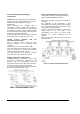
PLANCHER CHAUFFANT DANS BÉTON RADIANT FLOOR IN CONCRETE 120F/49C MAX 110F/43C STD 100F/-38C 90F/32C MIN 80F/27C 70F/21C 80F 27C 70F 21C 60F 15C 50F 40F 30F 20F 10F 0F 10C 4C 0C -7C -12C -17C Température ext. / Outdoor temperature PLANCHER CHAUFFANT ENTRE SOLIVES RADIANT FLOOR BETWEEN JOISTS 140F/60C -10F -23C -20F -29C MAX STD 120F/49C MIN 110F/43C 100F/-38C 90F/32C 80F 27C 70F 21C 60F 15C 50F 10C 40F 4C 30F 0C 20F -7C 10F -12C 0F -17C -10F -23C -20F -29C Température ext.
ITEM DESCRIPTION Choose the units the user prefers to work with CHOICE DEFAULT °F or °C °F Radiant Floor in concrete Radiant Floor between joists Select the type of heating system on which the boiler will be installed. Cast iron radiator Hot water baseboards Adjust the maximum boiler target temperature required to adequately heat the building when the outdoor temperature is very cold.
4.8.2 ’’Boost system operation’’ The controller incorporates a unique feature that enables the target boiler temperature to automatically be increased when the building heat load increases but cannot be fulfilled with the actual boiler target temperature and consequently the room thermostat(s) cannot be satisfied within a pre-determined period. Example : Return to normal heat load after low demand periods occurring during sunny days.
Section 5: START UP OPERATION ! SAFETY PRECAUTIONS Before operating this boiler, be sure to read and follow these instructions, as well as the warnings printed in this manual. Failure to do so can result in unsafe operation of the boiler resulting in property damage, bodily injury, or death. Should you have any problems reading, following or difficulty in understanding the instructions in this manual, STOP, and get help from a qualified person. Do not turn on the boiler unless it is filled with water.
Section 6: MAINTENANCE 6.1 INTRODUCTION Properly maintained, your boiler will provide years of dependable, trouble free service. It is recommended that a regular routine maintenance program be established and followed by the user. Components are subject to eventual failure that requires service. Failure to use the correct procedures or parts in these circumstances may make the unit unsafe or reduce the life of the boiler.
6.2 REPLACEMENT PARTS Temperature and Pressure Indicator ZMC300-75P160CN Pressure Relief Valve ZMC200-SV30PSI1 Control Module ZEL100-ULTRA Power Relays 24Vac ZEL100-24ACNO30 Transformer 208/240Vx24V (40va) ZEL400- 20842440 Fuse ZEL250-TDMIDJ5 2 Poles Contactor 24Vac (3, 4.5, 6, 7.5, 9 kW) ZEL100-2PC5024 4 poles Contactor 24Vac (12 kW) ZEL100-4P50A24 Figure 11 : Replacement Parts (Front view) Heating Elements** 3 kW : ZEL300-240V3KW 4.
Section 7 : TROUBLESHOOTING PROBLEM CAUSES SOLUTION The display shows --in “TARGET TEMP” -There is no heating demand -When the outdoor sensor is used and the icon is shown, the outside temperature is above the boiler shut down setting. -The switch located on the back of the controller is set to “Bi-Energ” and the -Generate a heat demand -Temporarily increase the value of this setting on the controller configuration. The display shows “Er1” and the icon icon is shown.
Boiler safety valve is leaking -Pressure reading at the indicator shows a pressure above 28 psi. -Pressure is below 28 psi -The pressure regulator on the distribution system is defective or the expansion tank is too small or defective. -Replace the safety valve Table 4: Sensors resistance value vs real temperature.
MINI ULTRA LIMITED WARRANTY Warranty Coverage on the tank. Thermo 2000 Inc. hereby warrants that the MINI ULTRA tank on normal use and service will not leak for a period of fifteen (15) years from the date of purchase. The warranty is valid as long as the original residential purchaser owns the building in which the unit was originally installed.