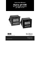
Instruction Manual Alpha pH 600 RF Transmitter System pH / ORP / ºC / ºF 68X450201 | Rev.
Preface This manual serves to explain the use of the Alpha pH 600 Series RF transmitter. It functions in two ways, firstly as a step by step guide to help you to operate the transmitter. Secondly, it serves as a handy reference guide. It is written to cover as many anticipated applications of the transmitter as possible. If there are doubts in the use of the transmitter, please do not hesitate to contact the nearest Authorized Distributor.
TABLE OF CONTENTS 1 INTRODUCTION 1.1 1.2 1.3 1.4 Before You Begin ........................................................................................... 1 Intended Use.................................................................................................. 1 Safety Instructions.......................................................................................... 2 Taking Out of Service / Correct Disposal of the Unit ..................................... 2 1 2 GETTING STARTED 2.1 2.
1 INTRODUCTION 1.1 Before You Begin Thank you for choosing the Alpha pH 600 Series RF Transmitter. The construction of Alpha pH 600 Series employs leading edge technology and complies with safety regulations currently in force. Notwithstanding this, improper use could lead to hazards for the user or a third-party, and/or adverse effects on the plant or other equipment. Therefore, the operating instructions must be read and understood by the persons involved before working with the pH Transmitter.
all information and warnings in the documentation dealing with the products used together with this pH / ORP Transmitter (housing, sensors, etc.). the local environmental and operational conditions. 1.3 Safety Instructions 1.4 The Alpha pH 600 RF Transmitter should be installed and operated only by personnel familiar with the instrument and who are qualified for such work. A defective pH 600 RF Transmitter must neither be installed nor put into service.
2 GETTING STARTED 2.1 Description of Instrument The Alpha pH 600 RF Transmitter is used for measuring pH or ORP and temperature values. The pH values can be measured using industrial combination pH sensors; the ORP values can be measured using industrial ORP sensor; the temperature values can be measured using 3-wire Pt100 / Pt1000 sensors.
2.
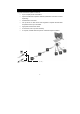
2.3 2.3.1 Connecting Peripherals Connection Terminals Remove Back Cover: • Remove the screws from the four corners at the back of the pH Transmitter. • Remove the back cover. The connectors are exposed on the back PCBA as shown in the Figure 1 below. Connectors: • J202 – 9V DC power • J204 - pH electrode & Temperature probe connections (wiring has to be done in the detachable connector: 1. Pin 1 : pH Sensor 2. Pin 2 : pH Reference 3. Pin 3 : No Connection 4. Pin 4 : No Connection 5.
2.3.2 Switching Between PT100 & PT1000 Temperature Sensors The Alpha pH 600 transmitter supports both Pt100 & Pt1000 (2-wire or 3-wire) temperature sensors. The default factory setting is Pt100. If you need to use Pt1000 temperature sensor, you have to change the jumper setting (J201) as described below. Remove Back Cover: Remove screws from the four corners at the back of the pH Transmitter. Remove the back cover. Remove Back PCBA: Remove the screw located center of the back PCBA (Figure 1).
2.3.3 Connecting pH/ORP Electrode 1. 2. If the pH/ORP electrode has a BNC connector, remove the BNC connector from the cable. NOTE: Oakton Instruments offers an optional ‘BNC to Spade Lug adapter’ (Order code: 05994-90) that can be used with pH/ORP electrode without removing the BNC connector. Strip the insulation of the cable so that the bare wires are exposed enough for connection as shown in Figure 3.
2.3.4 Connecting Temperature Probe For Automatic Temperature Compensated (ATC) pH readings, a 100Ω Pt RTD temperature probe (2-wire or 3-wire) can be connected to the Controller. 3-Wire Probe: 1. Connect PT100 compensate wire to Pin 5 of J204 connector 2. Connect PT100 sense wire to Pin 6 of J204 connector 3. Connect PT100 GND wire to Pin 7 of J204 connector 2-Wire Probe: 1. Short Pin 5 & 6 of J204 connector using a small piece of wire 2.3.5 2.
2.4 2.4.1 Installation Mechanical Dimensions Alpha pH 600 ESC CAL ENT PH/ORP RF Transmitter 2.4.
2.5 Display & Keypad 2.5.1 Display Overview The Liquid Crystal Display (LCD) of Alpha pH 600 Transmitter has two alphanumerical displays (Upper and a Lower). • Upper display: Measured pH, mV or relative mV value are displayed when the Transmitter is in normal operation (measurement) mode. • Lower display: Measured temperature value is displayed when the Transmitter is in normal operation (measurement) mode.
Mode Indicators MEAS Measurement mode; blinks in Symmetric mode (Refer Section 3.1& 5.5 ) SETUP Setup mode (Refer Section 5) CAL Calibration mode (Refer Section 4) Status Annunciators READY Appears when the reading is stable ATC Appears when Automatic Temperature Compensation (ATC) is enabled. Not visible when Manual Temperature Compensation (MTC) is enabled. Flashes if the temperature probe is faulty in its ATC mode. (Refer Section 5.3) ERR Appears when an error occurs (Eg.
2.5.2 Key Functions Alpha pH 600 ESC CAL ENT PH/ORP RF Transmitter Key Description Brings directly into the Calibration entry mode. The security code must be selected to enter the calibration mode or view only mode. CAL While in pH Measurement mode, press CAL to enter pH Calibration entry mode. While in mV Measurement mode, press CAL to enter mV Calibration entry mode. To confirm your calibration values in Calibration mode. To confirm selections in SETUP mode.
3 3.1 OPERATION Measurement mode When the pH Transmitter is powered on, the display shows all the LCD segments briefly, and then automatically enters into the Measurement mode. MEAS READY pH 7.00 25.0 °C ATC The mode indicator ‘MEAS’ at the top of the display indicates that the pH Transmitter is in Measurement mode; ‘MEAS’ blinks when in Symmetric mode. The upper alpha-numerical display shows the measured pH or mV value, while the lower display shows the temperature value.
3.2 Menu Overview 3.2.1 Alpha pH 600 CAL ENT CAL pH ENT MEAS Calibration See Section 4 pH °C ATC ENT SETUP ENT Offset Settings See Section 5.2 ENT Temperature Settings See Section 5.3 ENT ENT SETUP ENT SETUP ENT View Electrode Properties See Section 5.6 ENT Buffer Selection Settings See Section 5.
4 CALIBRATION MODE 4.1 Preparing the Transmitter & Electrode for Calibration Before starting calibration, make sure that the pH Transmitter is in appropriate measurement mode (pH or ORP). When the Transmitter is powered on, it starts up with the measurement mode last used. For example, if the pH Transmitter is powered off in ORP measurement mode, it starts up in ORP mode when it is powered on. (Refer Section 5.
CAL pH READY °C CAL ATC • • 4.3 ENT To exit Calibration mode at any time press ▲ and ▼ keys simultaneously (Escape). The calibration is always carried out in the units of measurement (pH or mV), selected in setup mode CAL pH HOLD pH Calibration The pH Transmitter is capable of calibration of up to 2 points using USA or NIST pH buffer standards. All new calibration values will automatically override the existing calibration data. pH buffer values are referenced to 25 oC.
1 From pH measurement mode press CAL key to enter calibration mode as described in section 4.2. The LCD shows ‘CAL PH’. Press ENT key to begin calibration. 2 Place the electrode in pH 7.00 buffer. Immerse the temperature probe in the buffer solution if ATC mode is enabled. Immerse the potential matching pin in the buffer if symmetrical mode is enabled. The buffer annunciator appears in LCD. Lower display shows pH 7.00 (USA standard buffer). Upper display shows the current uncalibrated pH reading.
when the reading is stable. Press ENT key to confirm the reading. 3 The pH Transmitter moves to the second calibration point. The lower display shows next standard buffer value (pH 4.01). Use ▲ and ▼ keys to select your second buffer from one of the preset values: pH 4.01 or 10.01. Remove the electrode from the first buffer, rinse and then immerse it into the second buffer. Allow the reading to stabilize. LCD shows ‘READY’ annunciator when the reading is stable.
1-Point Calibration: 1 2 CAL 3 CAL CAL pH ENT HOLD READY HOLD CAL 4 MEAS mV pH pH ENT HOLD READY °C °C pH ATC 1 From pH measurement mode press CAL key to enter calibration mode as described in section 4.2. The LCD shows ‘CAL PH’. Press ENT key to begin calibration. 2 Place the electrode in pH 6.86 buffer. Immerse the temperature probe in the buffer solution if ATC mode is enabled. Immerse the potential matching pin in the buffer if symmetrical mode is enabled.
pin in the buffer if symmetrical mode is enabled. The buffer annunciator appears in LCD. Lower display shows pH 6.86 (NIST standard buffer). Upper display shows the current uncalibrated pH reading. Allow the reading to stabilize. LCD shows ‘READY’ annunciator when the reading is stable. Press ENT key to confirm the reading. 3 The pH Transmitter moves to the second calibration point. The lower display shows next standard buffer value (pH 4.01).
4.4 Check Calibration MEAS CAL pH READY CAL mV ENT pH pH ATC ENT 1. While in Measurement mode press the CAL key. The display will prompt you to enter a security code. Leave the security code at “0” (view only mode). 2. Press the ENT key. The display shows the slope in mV (Main Reading) and the normalized temperature is shown on the Auxiliary reading of the display. NOTE: 4.5 To exit from any intermediate steps, press ▲ and ▼ keys (Escape) together. It will return to measurement mode.
5. 4.6 Press the ENT key to confirm. The transmitter calculates the correction factor and returns to the Measurement mode. Temperature Calibration Calibrate temperature probe only if temperature value displayed on the pH Transmitter is different from that of a calibrated thermometer. Refer to section 5.3 for further information temperature settings.
5 SETUP MODE 5.1 Enter Setup mode In the Setup mode the transmitter can be configured to the individual requirements. MEAS pH READY ENT ENT °C “User-setting” Mode (User can change parameter settings) ATC ENT “User-Setting” Mode (User can only view parameters) 1. While in measurement mode, press the ENT key. 2. The display prompts to enter the security code.
5.2 Electrode Offset Settings NOTE: ‘Electrode Offset Setting’ is not available when the pH Transmitter is configured for ORP measurement mode. (Refer Section 5.5 for switching measurement modes) In applications where continuous pH measurement is required, it may not be convenient to remove the electrode for calibration. In such cases, an on-line offset adjustment is recommended. The pH Transmitter allows you set an offset of up to ± 2.00pH to compensate for errors in the pH electrode.
‘READY’ annunciator when the reading is stable. Press ▲ or ▼ key to set the upper display to the newly calculated offset value. As the upper display value (offset) changes, the pH Transmitter adjust the lower reading automatically to suit the new offset value. Up to ± 2.00 pH offset is allowed. 3 Press ENT key to confirm the value. The pH Transmitter reverts to OFS screen. NOTE: 5.3 To exit from any intermediate steps, press ▲ and ▼ keys (Escape) together. It will return to measurement mode.
1 From pH or ORP measurement mode press ENT key to enter setup mode as described in section 5.1. The LCD shows the first screen of setup mode (OFS). Press ▲ or ▼ key to select Temperature settings screen (SET ºCF). Press ENT key to access temperature settings (SET ºCF). 2 Selecting unit of measurement for temperature: The upper display shows ‘Unit’ and the lower display shows the last configured unit of measurement for temperature. Press ▲ or ▼ key to select the desired units for temperature (ºC or ºF).
Setting calibration temperature: The lower display shows ‘C.ºC’ and the upper display shows the last configured calibration temperature. Press ▲ or ▼ key to adjust the upper display to desired calibration temperature. Allowable range: –10.0 to 110.0°C / 14.0 to 230°F. 7 Press ENT key to confirm the calibration temperature. The pH Transmitter reverts to SET ºCF screen. NOTE: Press ▲ or ▼ key to access other setup screens or press ▲ and ▼ key simultaneously (escape) to return to measurement mode.
From pH measurement mode press ENT key to enter setup mode as described in section 5.1. The LCD shows the first screen of setup mode (OFS). Press ▲ or ▼ key to select buffer settings screen (bUFF). 1 Press ENT key to access buffer settings (bUFF). Selecting buffer group: The lower display shows the last configured buffer group. Press ▲ or ▼ key to select the required buffer group (‘USA’ or ‘nST’). 2 Press ENT key to confirm your selection. The pH Transmitter reverts to bUFF screen. NOTE: 5.
SETUP SETUP SETUP ENT ENT SETUP SETUP ENT SETUP SETUP ENT SETUP SETUP Measurement Mode SETUP HOLD NOTE: To exit from any intermediate steps, press ▲ and ▼ keys (Escape) together. It will return to measurement mode. Selecting “pH” or “mV” Mode of Operation 1. Press ENT key and use ▲ or ▼ keys to scroll till LCD displays ‘CONF’ (Configuration). Press ENT again. 2. LCD displays ‘PH’. meter is set to operate as a pH meter.
In such cases, switch the Transmitter to the Symmetrical mode as below: 1. Press ENT key and use ▲ or ▼ keys to scroll till LCD displays ‘CONF’ (Configuration). Press ENT again. 2. LCD displays “ASY” (asymmetrical operation). Use ▲ or ▼ keys to select for ‘”SY” (symmetrical mode of operation). Press ENT key again. 3. Press S and T keys together to return to the CONF main mode. Selecting Back Light ON or OFF Operation 1.
5.6 Viewing Electrode Properties Each time you calibrate your pH electrode, the pH Transmitter re-calculates slope & offset of the electrode and shown in the LCD at the end of calibration. The setup mode allows you to view slope & offset values at any time. NOTE: When the measurement mode is set to ORP, only the offset value of the electrode is displayed.
6 T E C H N I C AL S P E C I F I C AT I O N S General Specification (a) pH pH Measuring Range Resolution Accuracy (b) mV mV Measuring Range Resolution Accuracy (c) Temperature Temperature measuring range Resolution Relative accuracy Sensor Compensation Calibration Point (a) pH Number of calibration points Number of calibration buffers (c) Temperature Offset Adjustment Input / Output Input Output 0.00 to 14.00 pH 0.01 pH ± 0.01 pH -1000 to 1000 mV 1 mV ± 1 mV -10.0 to +110.0 oC or +14.0 to +230.0 oF 0.
7 L I S T O F AC C E S S O R I E S 7.
7.2 Eutech Instruments pH Transmitter Replacement and Accessories Item Description Order Code Alpha pH 600 transmitter 56706-00 Wireless RF receiver with application software 56706-50 pH/Temp electrode with PMPO and 10-ft cable Platinium ORP electrode with 10-ft cable 35807-20 35801-21 BNC to spade lug adapter 05994-90 Calibration Solutions Item Description Order Code pH 4.01 calibration buffer, 500 ml pH 7.01 calibration buffer, 500 ml 00654-00 00654-04 pH 10.
8 TROUBLESHOOTING Problem Cause Solution Power on, but no display a) b) Loose connections Incorrect output voltage of the power adaptor a) Dirty electrode Electrical noise interference Electrical noise interference a) b) Ensure cables make good contact Use an power adaptor with specified output voltage Unstable pH reading a) b) Oscillating temperature readings a) Slow response a) Dirty / Oily electrode a) Clean electrode Blinking ATC a) a) Ensure temperature sensing cable makes good c
9 GENERAL INFORMATION 9.1 Warranty This transmitter is supplied with a one-year warranty against significant deviations in material and workmanship from date of purchase and a six-month warranty for probe. Each instrument will have a warranty card with a specific serial number. The warranty card must be endorsed by the Authorized Distributor at the point of sale.
APPENDICES 10 10.1 Appendix 1– pH Buffer Values at Various Temperatures The following table shows the various pH values at different temperature of the solution during calibration. 3 0 5 10 15 20 25 30 35 40 45 50 55 60 70 80 90 pH 4.01 4.01 4.01 4.00 4.00 4.00 4.01 4.01 4.02 4.03 4.04 4.06 4.08 4.10 4.12 4.16 4.20 pH 6.86 6.98 6.95 6.92 6.90 6.88 6.86 6.85 6.84 6.84 6.83 6.83 6.83 6.84 6.85 6.86 6.88 pH 7.00 7.12 7.09 7.06 7.04 7.02 7.00 6.99 6.98 6.97 6.97 6.97 6.97 6.98 6.99 7.00 7.
10.2 Appendix 2 – Abbreviations Used in LCD Abbreviation Description ASy Asymmetrical mode AtC Automatic Temperature Compensation bUFF Buffer CAL Calibration C.ºC Calibration temperature CONF Configuration dEF Default values FCt Factory (defaults) OFS Offset Or Reading is over range Orn Out of range OrP Oxidation Reduction Potential P.
Thermo Scientific Water Analysis Instruments North America 166 Cummings Center Beverly, MA 01915 USA Toll Free: 1-800-225-1480 Tel: 1-978-232-6000 Dom. Fax: 1-978-232-6015 Int’l Fax: 978-232-6031 www.thermo.com/process Europe Denmark House, Angel Drove Ely, Cambridgeshire CB7 4ET, UK Tel: 44-1353-666111 Fax: 44-1353-666001 Asia Pacific Blk 55, Ayer Rajah Crescent, #04-16/24 Singapore 139949 Tel: (65) 6778 6876 Fax: (65) 6773 0836 E-mail: eutech@thermofisher.com Oakton Instruments P.