ECM OPERATION MANUAL FOR USE WITH MODELS: OH5-85DE OH11-105DE OH2-56DE OC5-85DE OL5-85FDE OL11-105FDE OL2-56FDE OC2-56DE OL5-85RDE OL11-105RDE OL2-56RDE OH5-85DXE : IF YOU DO NOT FOLLOW THE SAFETY PRECAUTIONS BELOW AND IN THIS MANUAL, A FIRE OR EXPLOSION MAY RESULT CAUSING PROPERTY DAMAGE, PERSONAL INJURY, OR LOSS OF LIFE. DO NOT STORE OR USE GASOLINE OR OTHER FLAMMABLE VAPORS AND LIQUIDS IN THE VICINITY OF THIS OR ANY OTHER APPLIANCE.
All installations and services must be performed by qualified service personnel. INDEX SECTION BEGINNING PAGE I. FURNACE SPECIFICATIONS (SHIPPED SETTINGS) 1 II. BLOWER CONTROL INFORMATION A. TERMINAL DEFINITIONS & FIELD WIRING B. WIRING & SWITCHES C. INPUTS D. OUTPUTS E. OPERATING MODES F. CFM TABLES G. ECM SPECIFIC REPLACEMENT PARTS 4 4 5 9 9 10 12 13 III. ECM TROUBLESHOOTING A. DIAGNOSTIC FEATURES B. GENERAL GUIDELINES TO TROUBLESHOOTING GE ECM C.
All installations and services must be performed by qualified service personnel. I. FURNACE SPECIFICATIONS (SHIPPED SETTINGS) OL SERIES MODEL NO. HEAT INPUT RATE IN BTU/HR OL2-56 OL5-85 OL11-105 70,000 106,250 126,000 56,000 85,000 101,000 HEIGHT OF CASING WIDTH OF CASING DEPTH OF CASING WARM AIR OUTLET RETURN AIR INLET 34-3/4” 19” 48” 17 x 17 17 x 17 43-1/4” 25” 50-1/4” 20 x 20 20 x 14 46-1/2” 25” 54-1/2” 20 x 20 20 x 16 DIA.
All installations and services must be performed by qualified service personnel. OH SERIES MODEL NO.
All installations and services must be performed by qualified service personnel. OC SERIES MODEL NO. HEAT INPUT RATE IN BTU/HR OC2-56 OC5-85 70,000 106,250 56,000 85,000 HEIGHT OF CASING WIDTH OF CASING DEPTH OF CASING WARM AIR OUTLET RETURN AIR INLET 57-1/2” 19” 27” 17 x 17 17 x 17 56” 24” 33” 16 x 20 22 x 20 DIA. OF FLUE OUTLET FLOOR-CENTER OF FLUE 5” TOP 6” TOP COOLING COOLING 800 1000 1200 1400 800 1000 1200 1400 HEATING 737 HEATING 1134 HEATING CAPACITY IN BTU/HR FLOWRATE from .
All installations and services must be performed by qualified service personnel. II. BLOWER CONTROLLER INFORMATION A. TERMINAL DEFINITIONS & FIELD WIRING Burner Harness Connector P1 Pin 1 – Limit switch connection. Pin 2 – 120 VAC Line connection. Pin 3 – Burner pilot contact. Pin 4&5 – 120 VAC Neutral connection. Pin 6 – Burner pilot contact. Pin 7&8 – From oil primary control. Pin 9 – Limit Switch Input (LSI).
All installations and services must be performed by qualified service personnel. B.
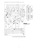
All installations and services must be performed by qualified service personnel. : TURN OFF THE ELECTRICAL POWER to the furnace before attempting to disconnect blower wiring.
All installations and services must be performed by qualified service personnel. : TURN OFF THE ELECTRICAL POWER to the furnace before attempting to disconnect blower wiring. OH5-85 DXE 2-STAGE Figure 3: BLOWER WIRING : TURN OFF THE ELECTRICAL POWER to the furnace before attempting to disconnect blower wiring.
All installations and services must be performed by qualified service personnel.
All installations and services must be performed by qualified service personnel. C. Inputs Power supplies Line voltage is applied between the "S1" and "N1" quick connect terminals. 24 VAC Class II Transformer secondary voltage supplied to X and C Limit Switch The 120VAC optically isolated limit switch input is connected on pin P2-1 & 9. Refer to the Heat Mode section for the control operation. Thermostat call for heat "W" 24 VAC thermostat input.
All installations and services must be performed by qualified service personnel. Compressor contactor The control provides switched 24VAC to operate a compressor contactor. Rating shall be class 2 - 24 VAC pilot duty @ 24 VAC (< 200mA). EAC (electronic air cleaner) The control provides a 120VAC output for an electronic air cleaner. This output is energized whenever the fan motor is energized (either low, heat or cool speed). Connection is made via male quick connect terminal labeled "EAC".
All installations and services must be performed by qualified service personnel. Anti-Short Cycle Operation To prevent compressor short cycling, a call for cooling will be ignored for four minutes after the termination of any cooling call. The anti-short cycle delay is also in effect at power-up. Heat Mode When a call for heat ("W") is received from the thermostat, if the “Cool” mode is not already active, the “T-T” terminal is energized and the blower on delay is started.
All installations and services must be performed by qualified service personnel. Speed Selection values Three dip switches select 8 cooling speeds. Dependant fan, and dehumidification speeds are selected by the same switches, their tabular values are enacted when their function is called. Three additional dip switches select 8 heating speeds which are enacted when heat is called. This allows independent selection of heating and cooling capacity parameters. See the CFM Tables for speeds. F.
All installations and services must be performed by qualified service personnel. OH5 2-STAGE OH5 2-STAGE SW1 SETTING 6 OFF 5 OFF 4 ON 6 OFF 5 OFF 4 ON 6 OFF 5 ON 4 ON 6 ON 5 OFF 4 OFF 6 ON 5 OFF 4 ON SW1 SETTING CFM TONS COOL LOW 2 726 352 2.5 924 462 3 1276 638 3.5 1474 726 4 1600 814 LOW FIRE CFM RISE 3 OFF 2 ON 1 OFF 3 OFF 2 ON 1 ON 3 ON 2 OFF 1 OFF HIGH FIRE CFM RISE 800 81 1008 78 905 72 1121 70 960 68 1200 66 Factory shipped settings G.
All installations and services must be performed by qualified service personnel. B. GENERAL GUIDELINES TO TROUBLESHOOTING GE ECM – DRIVEN SYSTEMS : Disconnect power from unit before removing or replacing connectors, or servicing motor. Wait at least 5 minutes after disconnecting power before opening motor.
All installations and services must be performed by qualified service personnel.
All installations and services must be performed by qualified service personnel. Figure 3: ECM PIN CONNECTORS Troubleshooting table above and Figure 2 adapted from GE Industrial Systems publication GED-7161C, “Troubleshooting GE ECM – Driven Systems”.
All installations and services must be performed by qualified service personnel. C. TROUBLESHOOTING CHARTS THIS GUIDE SHOULD BE USED IN THE CASE OF A STOPPED OR MANFUNCTIONED ECM BLOWER MOTOR. THE FOLLOWING SHOULD HELP ESTABLISH THE TYPE OF MALFUNCTION OR DEVIATION FROM THE NORMAL BLOWER OPERATION. TO USE THIS DIAGRAM, YOU JUST NEED TO FOLLOW THE INSTRUCTIONS IN THE BOXES. CONFIRM IF EITHER BLOWER WHEEL IS RUBBING AGAINST HOUSING OR MOTOR SHAFT IS SPINNING FREELY, REPAIR OR REPLACE AS NECESSARY.
All installations and services must be performed by qualified service personnel. Yes Sequence of Operation BLOWER OffDelay Active? No Yes HEAT Mode On? No Yes W Active? On-Delay Ended? No Yes Yes LIMIT Active? No No 1.BURNER Off 2. HEAT mode Off 3. BLOWER Off-Delay Started 4. Status LED Off BURNER On Yes Yes COOL Mode On? No Yes Y Active? On-Delay Ended? No Yes DEHUM Active? No No 1. A/C Off 2. COOL mode Off 3.BLOWER Off-Delay Started 4.
All installations and services must be performed by qualified service personnel. Sequence of Operation Glossary Inputs: LIMIT - 120vac power from the High Limit Switch used to power the burner. W- Switched 24vac indicating a Heat call from the thermostat. Y - Switched 24vac indicating a Cool call from the thermostat. G - Switched 24vac indicating a call for blower operation from the thermostat. DEHUM - Switched 24vac indicating a call for Dehumidification from a de-humidistat.