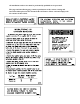
GAS-FIRED OR OIL-FIRED FURNACE DOWN FLOW & DIRECT VENT (SEALED COMBUSTION) MODELS: OMC-70 AND GMC-85 INSTALLATION AND SERVICE MANUAL For installation in: 1. Manufactured Homes 2. Modular Homes/Buildings 3. Site Construction—Residential (Single Story Dwellings) : FOR YOUR SAFETY Do not store or use gasoline or other flammable vapors and liquids in the vicinity of this or any other appliance. WHAT TO DO IF YOU SMELL GAS • Do not try to light any appliance.
All installations and services must be performed by qualified service personnel. I. SAFETY SECTION This page and the following two pages contain various warnings and cautions found throughout this furnace Service and Installation Manual. Please read and comply with the statements on the cover and the statements below. : All local codes and ordinances must be followed with regard to the oil tank and oil lines.
All installations and services must be performed by qualified service personnel. : If you do not follow these instructions exactly, a fire or explosion may result causing personal injury, loss of life or property damage. : NEVER use gasoline or a mixture of oil and gasoline to start the burner or furnace. : HAZARD OF ASPHYXIATION: Negative pressure inside the closet with closet door closed and the furnace blower operating shall be no more negative than minus 0.05 inch water column.
All installations and services must be performed by qualified service personnel. : If you suspect there is a problem with the furnace, the venting system or any other related problem, immediately contact a qualified service agency. If a service agency is not available contact your fuel supplier. : Personal injury, or property damage, could result from major repair or service of this furnace by anyone other than a qualified contractor.
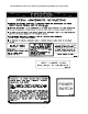
All installations and services must be performed by qualified service personnel. This page and the following page contain reproductions of the various warning and instruction labels placed on the Thermo Pride Oil Furnace. Please read and comply with the contents of these labels.
All installations and services must be performed by qualified service personnel.
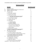
All installations and services must be performed by qualified service personnel. TABLE OF CONTENTS SECTION BEGINNING PAGE I. II. III. IV. SAFETY SECTION GENERAL INSTRUCTIONS AND CLEARANCES FURNACE SPECIFICATIONS INSTALLATION A. ROOF JACK B. STANDARD CHIMNEY C. FURNACE LOCATION D. BASE INSTALLATION 1. Combustible Floor Base Model: 70-BASE 2. Cottage Base Model: OMCCOT-BASE E. ALCOVE INSTALLATION F. CLOSET INSTALLATION G. COMBUSTION AIR H. FUEL PIPING 1. General Gas Piping 2. Oil Tank and Piping J.
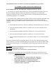
All installations and services must be performed by qualified service personnel. II. GENERAL INSTRUCTIONS AND CLEARANCES NOTE: READ THIS SECTION BEFORE STARTING INSTALLATION 1. The selection of a furnace heating capacity for a proposed installation should be based on a heat loss calculation made according to the manuals provided by the Air Conditioning Contractors of America (ACCA) or the American Society of Heating, Refrigeration and Air Conditioning Engineers, Inc. (ASHRAE). 2.
All installations and services must be performed by qualified service personnel. b. Non-combustible material: “...material that is not capable of being ignited and burned; such as material consisting entirely of, or a combination of, steel, iron, brick, concrete, slate, asbestos, glass, and plaster.” This heating appliance must be installed with clearances to combustible material surfaces of not less than the minimum distances given below.
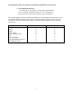
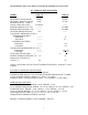
All installations and services must be performed by qualified service personnel. III. FURNACE SPECIFICATIONS MODEL OMC-70 GMC-85 HEAT INPUT RATE (BTUH) 85,000 HEATING CAPACITY (BTUH) 71,000 BURNER NOZZLE (GPH X ANGLE, HOLLOW CONE) 0.65X80A BURNER ORIFICE-NAT. GAS --------BURNER ORIFICE-PROP. GAS --------OIL PUMP PRESSURE (PSIG) 100 GAS SUPPLY PRESSURE (IN.W.G.) MINIMUM REQUIRED PROPANE --------NATURAL --------MAXIMUM ALLOWED PROPANE --------NATURAL --------GAS MANIFOLD PRESSURE (IN. W.G.
All installations and services must be performed by qualified service personnel. BURNER DATA OMC-70 GMC-85 MANUFACTURER: R.W. BECKETT CORP. MODEL: AFG AIR TUBE LENGTH (IN.): 3-5/8 HEAD DESIGN: F-3 REFRACTORY TYPE: MHC (FIBER) OIL PUMP PRESSURE (P.S.I.G.) 100 WAYNE COMBUSTION SYSTEMS P265 FEP 3-5/8 -------MHC (FIBER) -------- FOR BURNER COMBUSTION INFORMATION, REFER TO SECTION (M) – FLUE GAS COMBUSTION ANALYSIS. BLOWER DATA MANUFACTURER: MORRISON PRODUCTS, INC.
All installations and services must be performed by qualified service personnel. IV. INSTALLATION A. ROOF JACK The roof jack assembly and accessories must be listed by a nationally recognized testing agency for the appropriate fuel. The roof jack assembly must be installed according to the vent manufacturer’s instructions prior to the furnace installation. (Refer to Figure 2 for flue location on furnace.
All installations and services must be performed by qualified service personnel. Combustible Floor Base Model: 70-BASE Figure 1A.
All installations and services must be performed by qualified service personnel. Figure 1B. D. BASE INSTALLATION 1. Combustible Floor Base Model: 70-BASE Referring to Figure 1A, for applications using a combustion air channel and a supply air duct, use the base as a template to mark the floor opening locations. See Figure 2 for cutout locations. Cut a square opening in the floor for the supply air duct. Cut the opening 1-inch larger than the square template opening. Cut the combustion air duct opening.
All installations and services must be performed by qualified service personnel. If the combustion air passageway cannot terminate outside of the skirting or enclosure, a permanent opening with a minimum of 50 square inches of unobstructed infiltration (free area) for ventilation air must be provided for adequate combustion. This permanent opening must be located no less than 12 inches from the bottom of the enclosure or skirting. Figure 3. Slit the corners of feeder duct down to the top of the top panel.
All installations and services must be performed by qualified service personnel. IMPORTANT: Adequate combustion air must be provided under all circumstances. If the underside of the home is skirted or enclosed (e.g. by an enclosed crawlspace), the combustion air intake should exit through the side of cottage base and terminate outside of the structure.
All installations and services must be performed by qualified service personnel. E. ALCOVE INSTALLATION In this application, a minimum of 18 inches of clearance must be provided to the front of the unit. Refer to Figure 4. Alcove installations must use the No. 70 mobile home base. Refer to section G. COMBUSTION AIR for additional combustion air requirements. Figure 4. F.
All installations and services must be performed by qualified service personnel. 2. The return air opening may be located in the top, the center or (ideally) the bottom of the closet door, or side wall. : Do not obstruct any return air openings, including the return grille on the furnace. To do so may cause the furnace to activate the high temperature limit and shutdown, or it may cause asphyxiation. 3.
All installations and services must be performed by qualified service personnel. The preferred location of the outside combustion air intake termination (e.g. an optional stainless steel intake hood, part no.370183) is through the side of the structure, skirting or enclosure. An alternate termination location is under the structure in the skirted or crawlspace area providing a minimum of 50 square inches of free area exists around the perimeter for outside combustion air to be drawn through.
All installations and services must be performed by qualified service personnel. Figure 6.
All installations and services must be performed by qualified service personnel. H. FUEL PIPING Sizing and installation of fuel lines must be in accordance with federal, state and local regulations. 1. General Gas Piping (GMC-85) : Because of the potential of the odorant to fade, a gas leak may not be detected by smell. If this furnace is installed below grade, contact your gas supplier for a gas detector. A qualified installer or service person must install all gas piping and perform all required testing.
All installations and services must be performed by qualified service personnel. : The furnace and its gas valve must be disconnected from the gas supply during pressure testing of the gas supply system at pressures in excess of 1/2 PSIG (13.9 inches W.G.). The furnace can be isolated from the gas supply by closing the manual gas shutoff valve serving the appliance at test pressures equal to, or less than, 1/2 PSIG or (13.9 inches W.G.).
All installations and services must be performed by qualified service personnel. If possible, install the tubing under the floor. Specific information on piping, fuel pump connections, lift capabilities and tank installations is provided in the fuel pump manufacturer’s instructions. If the oil tank is located inside the building and the tank capacity is between 10 and 660 gallons, it shall not be located within 5 feet horizontally from any source of heat, or oilburning appliance.
All installations and services must be performed by qualified service personnel. Figure 7. J. ELECTRICAL WIRING All electrical wiring must be installed in strict accordance with local ordinances and codes. In the absence of local ordinances and codes, all electrical wiring must conform to the requirements of the National Electric Code, ANSI/NFPA 70-1999, or latest edition. : When testing electrical equipment, always follow standard electrical procedures and precautions.
All installations and services must be performed by qualified service personnel. 1. Electrical Branch Supply Circuit Route all electrical wiring to the left side of the furnace. The power supply circuit to the furnace must be installed and grounded in accordance with the provisions of the National Electrical Code, ANSI/NFPA-70-1999, or latest edition, and all local codes having jurisdiction. 2. Connection Of Power Supply Wires a. Remove the furnace control panel cover. b.
All installations and services must be performed by qualified service personnel. Once the furnace is installed, check the thermostat anticipator the proper nominal setting. a. Connect a multimeter, capable of reading milliamps (mA), in series with the low voltage wires to the thermostat. b. Increase the thermostat setting, or create a “call for heat”. c. Read the value of the thermostat current, in milliamps. d. Adjust the heat anticipator of the thermostat to the value read by the multimeter.
All installations and services must be performed by qualified service personnel. 4.
All installations and services must be performed by qualified service personnel. K. BURNER INSTALLATION The burner mounts to the furnace on three mounting bolt studs, located on the burner mounting plate, in the lower portion of the vestibule, directly in front of the heat exchanger. The burner insertion depth has been fixed by the factory for the design-specified, combination of the air tube length and the combustion chamber used with the furnace.
All installations and services must be performed by qualified service personnel. 8. The furnace is now ready for burner adjustment, refer to the following “BURNER OPERATION AND ADJUSTMENT” section. L. BURNER OPERATION AND ADJUSTMENT : NEVER burn garbage or refuse in the furnace. NEVER try to ignite oil or gas by tossing burning papers or other material into your furnace.
All installations and services must be performed by qualified service personnel. replacement parts for location identification). After the furnace is warmed up to a steadystate condition (about 15 minutes), the final burner adjustment should be made using combustion instrumentation for measuring carbon dioxide (CO2) or oxygen (O2), carbon monoxide (CO), smoke (for oil furnaces), and stack temperature. In order to achieve the most efficient combustion possible, the following steps must be taken.
All installations and services must be performed by qualified service personnel. The temperature rise across the furnace heat exchanger operating at steady-state conditions (about 15 to 20 minutes) should not exceed 100°F. The normal comfort range is between 70°F to 100°F. A lower temperature rise usually results in a higher system efficiency.
All installations and services must be performed by qualified service personnel. V. DEALER MAINTENANCE THIS SECTION IS ONLY TO BE PERFORMED BY TRAINED, QUALIFIED SERVICE PERSONNEL, AND NOT BY THE FURNACE OWNER. A. TROUBLESHOOTING : When testing electrical equipment, always follow standard electrical procedures and precautions. 1. Check for line voltage (110-120VAC) to the furnace.
All installations and services must be performed by qualified service personnel. OMC/GMC TROUBLESHOOTING FLOWCHART Set thermostat subbase to "HEAT" Does thermostat make contact? No Is room temperature above 90 deg. F? Yes Wait for room air to cool. No Yes Yes Is room temperature above thermostat setting? Turn thermostat setting above room temp. No Replace thermostat Does a "call for heat" initiate an ignition cycle? No Yes Turn power switch "on".
All installations and services must be performed by qualified service personnel. Are the thermostat wires connected properly? No Correct wire connections. Yes Yes Is the transformer (GMC) or oil primary control (OMC) supplying 24 VAC to the thermostat? Yes Replace thermostat. No Replace control transformer (GMC) or try resetting the oil primary control (OMC). Replace the oil primary control, if necessary.
All installations and services must be performed by qualified service personnel. After pre-purge, does the ignition control (GMC) or the oil primary (OMC) produce a spark at the ignition electrodes? No Is there 24 VAC across the power terminals of the ignition control module (GMC) or 120 VAC across the ignition transformer (OMC)? No On the GMC,has the burner motor centrifugal switch closed? If 120 VAC is measured across the switch, replace the burner motor. Else, replace thermostat.
All installations and services must be performed by qualified service personnel. No After fuel valve opens, does the burner ignite? For the GMC, measure gas supply pressure at inlet to gas valve. Is it at least 4.5" W.G. for natural gas or 11" W.G. for L.P. gases? For the OMC, is oil present in the fuel line at the valve? No Check the fuel supply. Open all manual shutoff valves serving the unit. Purge any air in the fuel line.
All installations and services must be performed by qualified service personnel. Yes Does system run until thermostat is satisfied? No Has the high limit thermostat or auxiliary high limit thermostat activated? No Check all wiring for loose connections. Yes Check for reduced airflow through the furnace. This may be caused by an excessively restrictive duct system, an inadequate amount of supply air,especially for furnaces installed in closets, or extremely dirty air filters.
All installations and services must be performed by qualified service personnel. B. CAD CELL CHECKOUT PROCEDURE: (OMC ONLY) 1. Remove cad cell lead wires, then start the burner. Shortly after burner starts, place a temporary jumper between terminals f & f of the oil primary control. Connect ohmmeter across cad cell lead wires - resistance should be less than 1600 ohms. 2. Stop the burner and remove temporary jumper. 3. With the burner off, check dark cell resistance across cad cell lead wires.
All installations and services must be performed by qualified service personnel. C. HEAT EXCHANGER CLEANING INSTRUCTIONS : The heat exchanger must be cleaned by a qualified service person. For oil-fired units, it is important to inspect and clean the heat exchanger once a year, or as necessary, to remove any build-up of soot.
All installations and services must be performed by qualified service personnel. Figure 8. Reassemble the furnace to the original factory-built condition. Remount the burner, being certain that the air tube is properly inserted into the chamber opening. If heavy soot deposits were found in the heat exchanger, this indicates that the burner may be out of adjustment. Reset the burner, as indicated under the “BURNER OPERATION AND ADJUSTMENT”, SECTION L. D.
All installations and services must be performed by qualified service personnel. Check all flue pipes for restrictions due to soot, or carbon build-up, as well as foreign matter, or any materials, that cause the venting system to restrict the proper venting of combustion products. If a restriction is found, the flue pipe must be cleaned or replaced to ensure proper venting.
All installations and services must be performed by qualified service personnel. VI. USER INFORMATION SECTION A. WARNINGS AND CAUTIONS: : If you suspect there is a problem with the furnace, pertaining to the venting system or any other related problem, immediately contact a qualified service agency. If a service agency is not available, contact your fuel supplier. : Personal injury or property damage could result from major repair or service of this furnace by anyone other than a qualified contractor.
All installations and services must be performed by qualified service personnel. B. COMPONENT LOCATIONS The following diagram shows a typical furnace installation and typical position of the components referenced in these instructions. Figure 9. C. INSPECTION AREAS IMPORTANT: For safe operation it is the responsibility of the owner and/or user that the burner, chimney/vent pipe, heat exchanger and controls should be inspected every year by a qualified heating contractor. 1.
All installations and services must be performed by qualified service personnel. 2. EXTERIOR OF FURNACES: The furnace exterior should be inspected for signs of excessive heat such as discoloration of materials or damage from rust or corrosion. 3. VENT CONNECTOR: The furnace vent pipe should be inspected for signs of rust, corrosion pitting, or holes in the pipe. Check for leakage around seams in pipe indicated by soot or condensate streaks. 4.
All installations and services must be performed by qualified service personnel. APPENDIX A.
All installations and services must be performed by qualified service personnel.