TWO STAGE CONDENSING GAS FURNACE INSTALLATION AND OPERATION MANUAL MODELS: FOR USE WITH NATURAL GAS CHX1-75N CHX1-100N CHX1-125N OR LP GAS (PROPANE) CDX1-75N CDX1-100N CDX1-125N : IF YOU DO NOT FOLLOW THE SAFETY PRECAUTIONS BELOW AND IN THIS MANUAL, A FIRE OR EXPLOSION MAY RESULT CAUSING PROPERTY DAMAGE, PERSONAL INJURY, OR LOSS OF LIFE. DO NOT STORE OR USE GASOLINE OR OTHER FLAMMABLE VAPORS AND LIQUIDS IN THE VICINITY OF THIS OR ANY OTHER APPLIANCE.
All installations and services must be performed by qualified service personnel. I. SAFETY INFORMATION This and the following page contain reproductions of the various warning and instruction labels placed on the Thermo Pride Two Stage Condensing Gas Furnaces. Please read and comply with the contents of these labels.
All installations and services must be performed by qualified service personnel. This and the previous page contain reproductions of the various warning and instruction labels placed on the Thermo Pride Two Stage Condensing Gas Furnaces. Please read and comply with the contents of these labels. The following safety information should be read, understood, and followed by the installer.
All installations and services must be performed by qualified service personnel. 1. Use only with type of gas approved for this furnace. Refer to furnace rating plate. 2. Connect this furnace to an approved vent system only. Combustion products must be carried outdoors. Refer to Section III, D thru H, of this manual. The following pages contain various warnings and cautions found throughout the Thermo Pride Highboy and Dual Poise Two Stage Condensing Gas Furnace Manual.
All installations and services must be performed by qualified service personnel. : Personal injury or property damage could result from repair or service of this furnace by anyone other than a qualified heating contractor. Only the homeowner/user routine maintenance described in the Users Information Manual may be performed by the user.
All installations and services must be performed by qualified service personnel. INDEX BEGINNING PAGE SECTION I. II. III. IV. V. VI. SAFETY INFORMATION FURNACE SPECIFICATIONS GENERAL INSTALLATION A. CODES AND CLEARANCES B. FURNACE LOCATION B1.CDX1 HORIZONTAL APPLICATION C. REPLACING EXISTING FURNACE FROM A COMMON VENT D. GENERAL REQUIREMENTS FOR VENTING CHX1/CDX1 E. SIDEWALL VENTING E1. SINGLE PIPE (SIDEWALL) VENTING OPTION F. INSTALLATION OF OUTSIDE VENT/AIR INTAKE TERMS. G.
All installations and services must be performed by qualified service personnel. II. FURNACE SPECIFICATIONS CHX1 SERIES MODEL NO.
All installations and services must be performed by qualified service personnel. CDX1 SERIES MODEL NO.
All installations and services must be performed by qualified service personnel. INSTALLATION PARTS PACKAGES – CHX1-75 PARTS PACKAGE #S00S4378 DESCRIPTION 2-3/8” ID radiator hose Thermostat lead bushing PVC trap assembly #8 x ¾ coated TEK screws for mounting trap & inlet/outlet collars 11/16” OD x 1/2” ID vinyl tubing 2 x 4 electrical J-box 2 x 4 electrical J-box cover #8 x ½ TEK screws for mounting 2 x 4 J-box #10-32 x ½ green ground screw #10-32 hex nut 3/16” dia.
All installations and services must be performed by qualified service personnel. INSTALLATION PARTS PACKAGES – CDX1-75 PARTS PACKAGE #S00S4380 DESCRIPTION 2-3/8” ID radiator hose Thermostat lead bushing PVC trap assembly #8 x ¾ coated TEK screws for mounting trap & inlet/outlet collars 11/16” OD x ½” ID vinyl tubing 2 x 4 electrical J-box 2 x 4 electrical J-box cover #8 x ½ TEK screws for mounting 2 x 4 J-box #10-32 x ½ green ground screw #10-32 hex nut 3/16” dia.
All installations and services must be performed by qualified service personnel. INSTALLATION PARTS PACKAGES – CDX1-100-125 PARTS PACKAGE #S00S4381 DESCRIPTION 2-3/8” ID radiator hose Thermostat lead bushing PVC trap assembly #8 x ¾ coated TEK screws for mounting trap & inlet/outlet collars 11/16” OD x 1/2” ID vinyl tubing 2 x 4 electrical J-box 2 x 4 electrical J-box cover #8 x ½ TEK screws for mounting 2 x 4 J-box #10-32 x ½ green ground screw #10-32 hex nut 3/16” dia.
All installations and services must be performed by qualified service personnel. III. GENERAL INSTALLATION These Category Type IV furnaces are shipped completely assembled and wired (internally). See the Dealer Receiving and Freight Claim Procedure Section of the price guide for parts shortage or damage. The furnace and duct system must be adjusted to obtain a temperature rise of 55°F to 85°F through the furnace after installation. (See rating label located on side panel inside the furnace vestibule).
All installations and services must be performed by qualified service personnel. Equipment must be installed in accordance with regulations of the National Board of Fire Underwriters. Authorities having jurisdiction should be consulted before installations are made. B. FURNACE LOCATION : These high efficiency condensing furnaces are not certified for and shall not be vented into a standard or any type of chimney. The following shall be considered for locating the furnace: 1.
All installations and services must be performed by qualified service personnel. NOTE: When the CDX1 is installed as horizontal unit, it is imperative that the auxiliary limit switch and bracket be located on the upper side of the house air blower; the burner rollout switch located on the burner box be relocated to the side of the burner box; and that the hose from the single tap pressure switch be connected to the lower tap on the front of the collector box (See Figure 1).
All installations and services must be performed by qualified service personnel. Equipment must be installed in accordance with regulations of the National Board of Fire Underwriters and the National Fuel Gas Code. Authorities having jurisdiction should be consulted before installations are made. C. REPLACING AN EXISTING FURNACE FROM A COMMON VENT : These furnaces may not be common vented with any other appliance. D.
All installations and services must be performed by qualified service personnel. NOTES: 1 The drain tee supplied with CHX1/CDX1 furnaces count as 1 elbow. 2 (2) 45° elbows can be substituted for (1) 90° elbow. Care should be taken to plan out the vent system to be as short as possible (but not shorter than 8 ft.) and to contain as few elbows as possible to insure the best possible operation of the furnace. 8. A hack saw may be used to cut the PVC pipe.
All installations and services must be performed by qualified service personnel. NOTICE: If exterior sidewall building materials are subject to degradation from flue gases or moisture, a minimum 12” diameter shield made from stainless steel or high density plastic shall be used for protection. 2. The PVC vent termination elbow must be installed in accord with local codes and these instructions. The bottom edge of the vent termination elbow must be installed at least 12 in.
All installations and services must be performed by qualified service personnel. Figure 4 : The vent and air intake elbows must be kept away from bushes, shrubs or any vegetation that may restrict the flow of flue products. It must also be kept clear of any leaves, weeds or other combustible materials. Keep the vent hood clear of snow. Avoid locating the terminals in areas where standing water or condensate drippage may be a problem.
All installations and services must be performed by qualified service personnel. F. INSTALLATION OF OUTSIDE VENT/AIR INTAKE TERMINATIONS NOTICE: Installation of the outside exhaust and combustion air vents must be performed by a qualified installer or service person in accord with local codes, the National Fuel Gas Code (NFPA 54, ANSI Z223.1 or latest edition) and the sections on venting in this manual. 1.
All installations and services must be performed by qualified service personnel. G. CONNECTING FURNACE TO THE VENT/AIR INTAKE TERMINATION AND DRAIN 1. The following diagrams show the typical vent and air inlet connection for a CHX1 and CDX1 furnace as well as a list of the parts that will be needed to install each.
All installations and services must be performed by qualified service personnel.
All installations and services must be performed by qualified service personnel. Figure 8 2. CONNECTING THE EXHAUST VENT TO THE INDUCER a. Insert the end of the 2”dia. PVC elbow (2" dia. PVC tee assembly for CDX1 horizontal installations) onto the outlet of the inducer blower assembly. Measure the length of 2” dia. PVC pipe needed to clear the furnace side casing, while allowing for the 2-3/8” rubber radiator hose to be installed within the casing of the furnace. Cut the 2” dia.
All installations and services must be performed by qualified service personnel. IMPORTANT: Horizontal installations of CDX1-100 and CDX1-125 units must utilize the 2" x 3" dia. PVC reducer as soon as the vent inlet exits the side casing of the unit. The CDX1-100 and CDX1-125 series units must be vented with 3" dia. PVC. Refer to Figure 8. b. After preparation of the 2” PVC pipe, use silicone type sealant on the 2” dia. PVC elbow (2" dia.
All installations and services must be performed by qualified service personnel. NOTICE: The exhaust vent piping must slope upward at least 1/4” per foot from the furnace to outdoor vent terminal. The inlet vent piping must slope downward at least 1/4” per foot from the beginning of the last horizontal run of pipe to the outdoor vent terminal. The PVC pipe must be supported directly over the vent tee assembly (CDX1) or (CHX1), every four feet thereafter and at every joint.
All installations and services must be performed by qualified service personnel. : Outside combustion air must not come from an area that is directly adjacent to a pool, hot tub or spa. Measures should be taken to prevent the entry of corrosive chemicals or vapors to the combustion and ventilation air supply. Such chemicals include but are not limited to chlorinated and/or fluorinated hydrocarbons such as found in refrigerants, aerosol propellants, dry cleaning fluids, degreasers and removers.
All installations and services must be performed by qualified service personnel. I. CONDENSATE DRAIN LINE AND TRAP ASSEMBLY 1. The following diagrams show the typical drain and trap connection for a CHX1 and CDX1 furnace. Figure 14. TRAP ASSEMBLY MOUNTED ON CHX1 Figure 15.
All installations and services must be performed by qualified service personnel. Figure 16. TRAP ASSEMBLY MOUNTED ON CDX1 RIGHT SIDE HORIZONTAL INSTALLATION 2. Determine on which side of furnace the condensate disposal line is to be run (NOTICE: On CHX1/CDX1’s this must be the same side as the flue outlet or bottom of unit). Attach the condensate trap to the furnace casing using the #8x3/4” sheet metal screws provided in the parts package. Pilot holes are provided on both sides of the casing for mounting.
All installations and services must be performed by qualified service personnel. 4. Measure the drain hose (11/16” o.d. clear tubing) provided and remove any extra length, making sure that the hose has sufficient length not to kink or otherwise be restricted once installed. Attach the drain hose (11/16” o.d. clear tubing) to the other side of the condensate trap tee.
All installations and services must be performed by qualified service personnel. Figure 18 2. A drip leg must be used on both LP and natural gas installations prior to the furnace in order to trap oil, condensate and other impurities which might otherwise lodge in the gas valve or plug the burner orifice. A drip leg shall be provided at the outlet of the gas meter when there is excessive condensation between the gas meter and the furnace.
All installations and services must be performed by qualified service personnel. This CHX1 furnace has been factory supplied with a high quality re-usable filter rated for air velocities up to 600 ft/min. An optional Thermo Products filter rack assembly (part no. AOPS7547 for CHX1-75 thru 100 and AOPS7375 for CHX1-125) is available which is sized for the filter provided.
All installations and services must be performed by qualified service personnel. 3. USE OF NON-THERMO PRIDE FILTER RETENTION MEANS If a method other than the Thermo Pride filter rack is selected for retention of the filter and/or use of a different filter type is desired, see Table 3 for minimum size guidelines for selecting a filter system for the CHX1 or CDX1 furnaces. MINIMUM FILTER AREA REQUIRED (LENGTH X WIDTH, SQ. IN.) TABLE 3 FILTER TYPE MAXIMUM Required CFM / (Filter Velocity Rating x 144) = min.
All installations and services must be performed by qualified service personnel. a. A separate power supply circuit with over current protection and a disconnect switch must be provided. The minimum fuse or circuit breaker size is 20 amp. b. All CHX1 and CDX1 Series furnaces are supplied with a fuse disconnect switch box to be mounted on the outside surface of the right or left side casing so a fuse disconnect can be mounted on the furnace. Make the 115 volt supply connection in this junction box.
All installations and services must be performed by qualified service personnel. 4. BLOWER AND CONTROL PANEL WIRING Figure 21 : TURN OFF THE ELECTRICAL POWER to the furnace before attempting to disconnect blower wiring. DIP SWITCH (S1): HEAT “OFF” DELAY SW1 SW2 SECS. ON ON 60 SEC. OFF ON 90 SEC. *ON OFF 120 SEC. OFF OFF 180 SEC. ND 2 STAGE DELAY FOR SINGLE STAGE THERMOSTATS SW3 MINUTES OFF 5 MIN. *ON 10 MIN.
All installations and services must be performed by qualified service personnel. Modifications to ECM blower speed settings are done using the S3 and S4 dip switch controls. (Labeled 1 to 8 in Figure 21). Thermo Pride two-stage furnaces are factory shipped at the CFM settings listed below in Table 4.
All installations and services must be performed by qualified service personnel. IV. STARTING THE UNIT A.
All installations and services must be performed by qualified service personnel. AFTER IGNITOR WARM-UP, THE 36E54 GAS VALVE IS ENERGIZED TO OPEN ON LOW FIRE SETTING FLAME MUST BE DETECTED WITHIN 4 SECONDS IF FLAME IS DETECTED, THE DELAY-TO-FAN-ON TIME BEGINS (45 SECONDS) IF NOT IF FLAME IS NOT DETECTED, THE GAS VALVE IS DE-ENERGIZED, THE IGNITOR IS TURNED OFF AND THE 50V61-143 CONTROL GOES INTO "RETRY" SEQUENCE THE RETRY SEQUENCE PROVIDES A 60 SECOND WAIT BEFORE IGNITION RETRY.
All installations and services must be performed by qualified service personnel. IF SYSTEM IS IN LOCKOUT, THE MODULE WILL RESET ITSELF AFTER 60 MINUTES OR MAY BE MANUALLY RESET BY INTERRUPTING THE POWER TO THE FURNACE AT THE DISCONNECT OR INTERRUPTING THE CALL FOR HEAT AT THE THERMOSTAT. IF THIS DOES NOT RESTART THE SYSTEM, REFER TO THE TROUBLESHOOTING SECTION OF THIS MANUAL.
All installations and services must be performed by qualified service personnel. B. INITIAL START UP: This furnace does not have a pilot. It is equipped with a hot surface igniter, which automatically lights the burner. Do not attempt to light the burner by hand. Check the following items before the initial start-up. 1. Check all wiring for loose connections and proper hook up. 2. Leak test gas piping connections. 3.
All installations and services must be performed by qualified service personnel. Measuring And Adjusting Heat Input Rate DO NOT exceed input rating stamped on furnace nameplate or manufacturer's recommended burner manifold pressure for orifice size used. Observe the following precautions when measuring: A. Burner manifold pressure with a pressure gauge. 1. Close the gas valve (turn the gas control knob to the OFF position) BEFORE removing the: a.
All installations and services must be performed by qualified service personnel. NOTICE: A U-tube manometer, measuring pressure in inches of water column, is recommended for all gas pressure measurements. However, an aneroid pressure gauge, in good working condition, capable of reading pressure changes of 0.05 in. W.G., or less, that was recently calibrated (within the last year), is a satisfactory alternate. These two (2) devices will be considered as equivalent and interchangeable.
All installations and services must be performed by qualified service personnel. 5. To obtain an accurate manifold gas pressure reading, the main burner must be cycled on and off several times to stabilize the gas control valve pressure regulator diaphragm. 6. Allow the burner to operate for at least 3 minutes before taking gas pressure readings. 7. Using a pressure gauge, measure the burner manifold gas pressure. 8. If checking the input rate by measuring burner manifold pressure, skip to step 12.
All installations and services must be performed by qualified service personnel. Figure 23: Outlet view of two-stage, automatic gas control valve b. Using a 3/32-in. hex key (or Allen wrench), turn the inner adjustment screw clockwise to increase, or counterclockwise to decrease, the gas pressure (and gas flow) to the main burner. c. Replace the cap screw and tighten it firmly to prevent gas leakage. d.
All installations and services must be performed by qualified service personnel. 17. If checking the input rate by measuring burner manifold pressure, proceed to step 18. If measuring the input rate by clocking the gas meter, repeat steps 9 through 11, above. 18. If the gas pressure is not within the specified high fire manifold pressure range (refer to Table 5), repeat steps 12(a) through 12(d), above, adjusting the high fire gas pressure regulator.
All installations and services must be performed by qualified service personnel. This furnace is designed not to require any burner adjustment. Burner aeration is fixed in this design. Burner flames can be seen by looking through the sight glass located on the burner box. Burner flames should be well-defined, light to medium blue in color, and almost transparent. (refer to Figure 24).
All installations and services must be performed by qualified service personnel. TIME (sec.) FLOW (cfh) 40 41 42 44 45 46 47 48 49 50 51 52 53 54 55 56 57 58 59 60 62 64 66 68 70 72 74 76 78 80 84 88 92 96 100 105 110 115 120 125 130 135 140 150 160 170 180 90 88 86 82 80 78 77 75 73 72 71 69 68 67 65 64 63 62 61 60 58 56 54 53 51 50 49 47 46 45 43 41 39 38 36 34 33 31 30 29 28 27 26 24 23 21 20 TABLE 6 - CONVERTING GAS FLOW RATE * For one cubic foot per revolution gas meter dials, use Table directly.
All installations and services must be performed by qualified service personnel. C. FURNACE CHECKOUT PROCEDURE Before any system of gas piping is finally put into service, it shall be carefully tested to assure that it is gas tight as indicated in the manual. NOTICE: All controls on the unit should be checked for proper functioning prior to the qualified service personnel leaving the job site.
All installations and services must be performed by qualified service personnel. 5. That failure to maintain and operate this furnace in accordance with these instructions could result in hazardous conditions, bodily injury, property damage and may void the limited warranty on the furnace. 6. Review with and encourage the user to read the label reproductions and all warnings and instructions outlined on the front cover and in sections I, II and III of this manual and in the Users Information Manual. 7.
All installations and services must be performed by qualified service personnel. DIAGNOSTIC FEATURES The 50V61 control used on this furnace continuously monitors its operation and the operation of the system. If the sensed failure is in the system (external to the control), the red LED will flash in the following flashpause sequences to indicate failure status (each flash will last approximately 0.
All installations and services must be performed by qualified service personnel. TROUBLESHOOTING GUIDE THE SYSTEM IS STARTED BY SETTING THE THERMOSTAT TO CALL FOR HEAT. THE FOLLOWING SHOULD HELP ESTABLISH THE TYPE OF MALFUNCTION OR DEVIATION FROM THE NORMAL OPERATION. NOTE: IF LED LIGHT IS FLASHING, REFER TO PAGE 34 FOR A QUICK TROUBLESHOOTING GUIDE. TO USE THIS DIAGRAM, YOU JUST NEED TO FOLLOW THE INSTRUCTIONS IN THE BOXES.
All installations and services must be performed by qualified service personnel. IS INDUCER RUNNING ON LOW SPEED? NO CHECK CONTACTS ON LOW FIRE PRESSURE SWITCH AND FOR BLOCKAGE IN FLUE. IF OK, REPLACE DUAL PRESSURE SWITCH. REPLACE THE 50V61-143 CONTROL.
All installations and services must be performed by qualified service personnel. IS IGNITOR POSITIONED CORRECTLY? NO REPOSITION TO CORRECT LOCATION YES CHECK AND CLEAN BURNERS DO BURNERS STAY LIT PAST PROOF OF FLAME CHECK? NO CHECK FOR PROPER LINE AND MANIFOLD PRESSURE REFERENCE GAS PRESSURE CHART PAGE 31.
All installations and services must be performed by qualified service personnel. IS THERE 24 VOLTS ACROSS "MVH" AND "MV COM" ON 50V61-143 CONTROL? NO REPLACE THE 50V61-143 CONTROL. YES CHECK CONNECTIONS TO GAS VALVE. IF OK, REPLACE GAS VALVE.
All installations and services must be performed by qualified service personnel. DOES BURNER SHUT OFF WHEN THERMOSTAT IS SATISFIED? NO CHECK FOR 24 VOLTS AT GAS VALVE. NO YES YES DOES THE CIRCULATING AIR BLOWER TURN OFF AFTER THERMOSTAT IS SATISFIED WITHIN 120 SECONDS? CHECK FOR SHORT IN WIRE TO THERMOSTAT AND CORRECT IF NECESSARY.
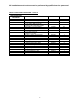
All installations and services must be performed by qualified service personnel. Appendix –A Replacement Parts List 1. Replacement parts list for CHX1-75, CHX1-100 and CHX1-125.
All installations and services must be performed by qualified service personnel.
All installations and services must be performed by qualified service personnel. 2. Replacement parts list for CDX1-75, CDX1-100 and CDX1-125.
All installations and services must be performed by qualified service personnel.
All installations and services must be performed by qualified service personnel.
All installations and services must be performed by qualified service personnel.