
INSTALLATION AND OPERATION MANUAL TWO STAGE CONDENSING GAS FURNACE CHX1-75N, CDX1-75N, CHX1-100N, CDX1-100N, CHX1-125N, CDX1-125N

All installations and services must be performed by qualified service personnel.
35
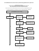
5. To obtain an accurate manifold gas pressure reading, the main burner must be cycled on and off
several times to stabilize the gas control valve pressure regulator diaphragm.
6. Allow the burner to operate for at least 3 minutes before taking gas pressure readings.
7. Using a pressure gauge, measure the burner manifold gas pressure.
8. If checking the input rate by measuring burner manifold pressure, skip to step 12. If
measuring the input rate using a gas meter, proceed to step 9.
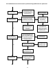
9. Using a clock (or watch) capable of measuring time in seconds, carefully clock the gas meter to
determine the time for one (1) complete revolution of the gas meter dial or reel. At least one (1)
cubic foot of gas flow should be measured. Use Table 6 to determine the main burner gas flow
rate in cubic feet per hour (CFH).
NOTICE: Some gas meters will require more than one (1) cubic foot of gas pass through the
meter for reasons of accuracy. When more than one (1) cubic foot of gas is consumed, divide the
total time by the number of cubic feet for comparison to the figures in Table 6.
10. Compare actual heat input rate with our recommended input (printed on the furnace rating label).
To convert the rating label input rate (given in BTUH) to the equivalent gas flowrate (in CFH), use
the following formula:
()
CFHinflowrategasFuel
ft
BTU
invalueheatinghighergasFuel
B
TUHinrateinput
H
ea
t
×
÷
÷
ø
ö
ç
ç
è
æ
=
3
)(
or,
()
÷
÷
ø
ö
ç
ç
è
æ
=
3
)(
ft
BTU
invalueheatinghighergasFuel
BTUHinrateinputHeat
CFHinflowrategasFuel
11. If the measured input rate is above, or below, the rating label value by more than 2%, adjust the
manifold gas pressure using the gas control valve pressure regulator to obtain the input rating
within a ± 2% range. Refer to steps 12(a) through 12(d).
12. If the gas pressure is not within the specified low fire manifold pressure range (refer to
Table 5), use the following procedure to adjust the low fire, gas pressure regulator to match the
specified low fire manifold pressure.
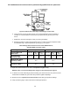
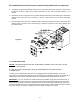
a. Remove the gas pressure regulator adjustment cap screw from the automatic gas control
valve. The cap screw is located on the outlet side of the valve. Refer to Figure 23.