
User Guide


All installations and services must be performed by qualified service personnel.
Once the furnace is installed, check the thermostat heat anticipator the proper nominal
setting.
a. Connect a multimeter, capable of reading milliamps (mA), in series with the low voltage
wires to the thermostat.
b. Increase the thermostat setting, or create a “call for heat”.
c. Read the value of the thermostat current, in milliamps.
d. Adjust the heat anticipator of the thermostat to the value read by the multimeter.
If the heat anticipator is set too high, the furnace may delay activation of a heating cycle for
too long. If the heat anticipator is set too low, the furnace may cycle too frequently. Either
condition may not provide optimal comfort to the homeowner.
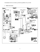
4. BLOWER CONTROLLER INFORMATION FOR PSC MOTOR
TERMINAL DEFINITIONS & FIELD WIRING
Burner Harness Connector P1
Pin 1- Limit switch connector.
Pin 2- 120 VAC Line connection.
Pin 3- Burner pilot contact.
Pin 4&5- 120 VAC Neutral connections.
Pin 6- Burner pilot contact.
Pin 7&8- From oil primary control.
Pin 9- Limit Switch Input (LSI).
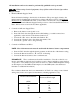
Field Wiring to Burner
Pilot (Tstat) Neutral Line
Yellow Wires White Red
Harness Wires
T-T terminals White Black
Beckett Connections
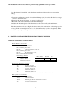
Thermostat / Humidistat connections
“C” Common / ground
“W” Thermostat call for heat
“R” 24 VAC to thermostat
“G” Thermostat call for fan
“Y” Thermostat call for cool
“DEHUM” Humidistat call for dehumidification (TXV systems ONLY)
Male quick connect terminals.
“S1-3” 120 VAC Hot
“N1-7” 120 VAC Neutral
“EAC” Electronic Air Cleaner (120 VAC) connection
“FAN” Fan On Signal
“X” 24 VAC from transformer
25