
Operating Instructions and Installation Instructions

Pag.21
Operation using control knobs. (See pages 17 and 22)
Three buttons are required for operation: - “UP” button – “DOWN” button – “RESET” button To start the system,
press the “UP” en “DOWN” buttons together for at least three seconds. The start-up process is indicated by a se-
ries of three short tones. After the flame has lit, it can be increased to the maximum height by pressing the “UP”
button. Pressing the “DOWN” button reduces the flame size to its minimum height. Pressing the “UP” and
“DOWN” buttons again for at least three seconds switches off the unit. In the event of a fault in the unit, the sys-
tem can be unlocked by pressing the “RESET” button and reset to the “STAND BY” state.
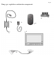
10.4 Gas connection
Mount the gas regulation combination in an accessible place near to the gas block fire (take account of the length
of the connection cables). Use a 1/2“ gas tap with a connector. Fit a (ø12mm) gas pipe between the gas regulation
combination and the Topper-
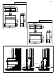
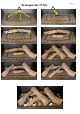
Pilot flame cover
burner. For model 9013 burner (B / P), mount the flexible gas pipe using
the accompanying radiator connection and nosepiece by first exchanging the flare fitting
for the accompanying nosepiece. Connect the pilot pipe and the ignition cable to the Oxy
stop pilot flame. Also ensure that the gas pipe is free from dirt or sand. You should ensure
that the various connection points are accessible. Ensure that the control equipment does
not become twisted during installation and that there is no excessive tension during con-
nection. After installation, check that the connections are gas tight. Position the pilot
flame cover as shown after the pilot flame burner has been assembled. The pilot flame
cover is not used on the 4525 and 9013 models.
Waakvlamkap
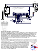
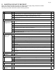
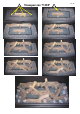
COMBINATION DIAGRAM
Dungs / Exhausto EFC 21